Base Stattion on Raspberry Pi 3 B+ board
Last update: 2022-06-29
Table of Content
Operating System#
-
Download Raspberry Pi Imager and install it.
-
Run the Pi Imager, and select the Desktop version but without recommended software.
-
Press
Ctrl + Shift + Xto show the advanced menu, fill some settings as below:- Hostname:
base - SSH:
yes- Default username:
pi, with passwordraspberry
- Default username:
- WiFi (optional): set SSID and password
- Hostname:
Alternative method using balenaEtcher
-
Download Raspberry Pi OS image, select Desktop version but without recommended software.
-
Download balenaEtcher and install it, and write the Image in an SD Card. After finishing, re-plug the SD Card.
-
Initial settings:
-
Default hostname:
raspberrypi.local -
Add an empty file with name
sshinto thebootpartition to enabled SSH.- Default username:
pi, with passwordraspberry
- Default username:
-
WiFi (optional): Enabling WiFi network by add a file
wpa_supplicant.confin thebootpartition:country=US ctrl_interface=DIR=/var/run/wpa_supplicant GROUP=netdev update_config=1 network={ ssid="NETWORK-NAME" psk="NETWORK-PASSWORD" }
-
-
Some tweaks can be applied after login
-
To use some list command, in
.bashrc, enable alias forlscommand. -
To disable animation on GUI:
gsettings set org.gnome.desktop.interface enable-animations false -
If
eth0is used, it may take priority of network connection over thewlan0. If internet is accessible throughwlan0, edit/etc/dhcpcd.confand add this:interface wlan0 metric 100Then wireless will have precedence, its default route/gateway will be used.
-
-
Enable GPIO and peripherals
-
The official tool
raspi-configshould be used to configure the Pi:sudo raspi-configSelect Interfacing Options and select below item:
- SPI →
Enable - I2C →
Enable - Serial Port → No login shell →
Enable
After enabling the primary UART, the VPU clock will be set at 250 MHz. CPU clock will not be affected. We aren’t going to use VPU, so it is acceptable to reduce its clock.
- SPI →
-
Run
groupsto see the current user is added into groups for using GPIO includinggpio,i2candspi.
-
UART Config#
Refer to Raspberry Pi UART.
There are two types of UART available on the Raspberry Pi - PL011 and mini UART. The PL011 is a capable, broadly 16550-compatible UART, while the mini UART has a reduced feature set. All UARTs on the Raspberry Pi are 3.3 V only.
The Raspberry Pi 3 has below default UART configuration:
| Port | Type | Usage | Pin Map | Linux Device |
|---|---|---|---|---|
| UART0 | PL011 | Secondary (Bluetooth), Enabled | N/A | /dev/serial1 |
| UART1 | mini UART | Primary, Disabled | GPIO 14 (TX), GPIO 15 (RX) | /dev/serial0 |
That means the exported UART port on GPIO header is a mini-UART. The problem is the speed of mini-UART port depends on VPU (graphic) Core Frequency.
The primary UART is disabled by default. It has to be enabled by running raspi-config to set up interfaces.
Use PL011 on the primary UART via Device Tree overlay
The two most useful overlays are disable-bt and miniuart-bt which can be added config.txt file, such as:
dtoverlay=disable-bt
The option disable-bt disables the Bluetooth device and makes the first PL011 (UART0) the primary UART. You must also disable the system service that initializes the modem, so it does not connect to the UART:
sudo systemctl disable hciuart
To get rid of using sudo permission, add current user into the serial group.
Run ls -al /dev/tty* to check the user group of ttyS0, ttyTHS1. Normally, it is needed to add current user into tty and dialout groups:
sudo usermod -a -G tty $USER && \
sudo usermod -a -G dialout $USER && \
sudo reboot
UART Testing
For testing, a serial terminal must be installed. Choose one of below.
putty
sudo apt install -y putty
putty
Follow GUI to run.
minicom
sudo apt install -y minicom
minicom -D /dev/ttyS0 -b 115200
Press Ctrl-A X to exit.
picocom
sudo apt install -y picocom
picocom /dev/ttyS0 -b 115200
Press Ctrl-A and Ctrl-X to exit.
screen
sudo apt install -y screen
screen /dev/ttyS0 115200
Press Ctrl-A K to exit.
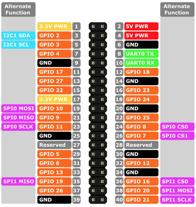
Module Connection#
Refer to below pinout diagram:

Serial driver#
Download source code and build:
git clone https://github.com/vuquangtrong/SerialPort.git && \
cd SerialPort && \
make && \
sudo make install
An example to communicate with Serial port:
// Serial library
#include "serial/SerialPort.h"
#include <unistd.h>
#include <stdio.h>

#define SERIAL_PORT "/dev/ttyS0"

int main( /*int argc, char *argv[]*/) {
    SerialPort serial;

    char errorOpening = serial.openDevice(SERIAL_PORT, 115200);
    if (errorOpening!=1) return errorOpening;
    printf ("Successful connection to %s\n",SERIAL_PORT);

    // Display ASCII characters (from 32 to 128)
    for (int c=32;c<128;c++)
    {
        serial.writeChar(c);
        usleep(10000);
    }

    // Read lines and print them out
    char line[1024];

    while(1) {
        int n = serial.readBytes(line, sizeof(line));
        if (n>=0) {
            std::cout << std::string(line, n) << std::endl;
        }
    }

    // Close the serial device
    serial.closeDevice();

    return 0 ;
}
Compile and run:
g++ example.cpp -lserial -o example
nRF24 driver#
Download source code from GitHub and build:
git clone https://github.com/vuquangtrong/RF24 && \
cd RF24 && \
./configure --driver=SPIDEV && \
make && \
sudo make install
SPIDEV must be used to avoid permission error when using default RPi BCM driver
Work with the original source code
GitHub at https://github.com/nRF24/RF24.
The guide to install in Linux at https://nrf24.github.io/RF24/md_docs_linux_install.html.
Download the install.sh file:
wget http://tmrh20.github.io/RF24Installer/RPi/install.sh
Make it executable:
chmod +x install.sh
Run it and choose the option:
- RF24 Core
- SPIDEV driver
./install.sh
Do you want to install GIT using APT (Used to download source code) [y/N]? n
Do you want to install the RF24 core library, [y/N]? y
Do you want to install the RF24Network library [y/N]?
Do you want to install the RF24Mesh library [y/N]?
Do you want to install the RF24Gateway library [y/N]?

Installing RF24 Repo...

__* Install RF24 core using? *__
1.BCM2835 Driver(Performance) 2.SPIDEV(Compatibility, Default)
3.WiringPi(Its WiringPi!) 4.MRAA(Intel Devices) 5.LittleWire
2
...
[Installing Libs to /usr/local/lib]
[Installing Headers to /usr/local/include/RF24]
make: Leaving directory '/home/pi/rf24libs/RF24'
Source to test data receiving. Check the transferring site in Rover.
#include <iostream>    // cin, cout, endl
#include <RF24/RF24.h>

// create RF24 instance
RF24 radio(24 /* CE = sys_gpio_24 */,
            0 /* CSN = 0 means spidev0.0 */
            /* default speed is 10 Mbps */);

// max payload of RF24 is 32 bytes
uint8_t payload[32];

int main(int argc, char** argv) {
    // perform hardware check
    if (!radio.begin()) {
        std::cout << "radio hardware is not responding!!" << std::endl;
        return 0; // quit now
    }

    radio.setPayloadSize(32);
    radio.setChannel(100); // 2400 + 100 = 2500 MHz, out of WiFi band

    // address, defaut length is 5
    uint8_t tx_address[6] = "1Addr"; // write to
    radio.openWritingPipe(tx_address); // always uses pipe 0

    // (smaller) function that prints raw register values
    radio.printDetails();
    // (larger) function that prints human readable data
    radio.printPrettyDetails();

    // Start
    std::cout << "Start TX" << std::endl;
    radio.stopListening(); // put radio in TX mode

    while(true) {
        radio.write(&payload, 32); // transmit
    }
}
Compile the source code:
arm-linux-gnueabihf-g++ -marm -march=armv6zk -mtune=arm1176jzf-s -mfpu=vfp -mfloat-abi=hard -Ofast -Wall -pthread rf24_tx.cpp -lrf24 -o rf24_tx
or just use:
g++ -Ofast -Wall -pthread rf24_tx.cpp -lrf24 -o rf24_tx
Run it and see the log:
================ SPI Configuration ================
CSN Pin         = /dev/spidev0.0
CE Pin          = Custom GPIO24
SPI Speedz      = 10 Mhz
================ NRF Configuration ================
STATUS          = 0x0e RX_DR=0 TX_DS=0 MAX_RT=0 RX_P_NO=7 TX_FULL=0
RX_ADDR_P0-1    = 0x7264644131 0x65646f4e31
RX_ADDR_P2-5    = 0xc3 0xc4 0xc5 0xc6
TX_ADDR         = 0x7264644131
RX_PW_P0-6      = 0x20 0x20 0x20 0x20 0x20 0x20
EN_AA           = 0x3f
EN_RXADDR       = 0x03
RF_CH           = 0x64
RF_SETUP        = 0x03
CONFIG          = 0x0e
DYNPD/FEATURE   = 0x00 0x00
Data Rate       = 1 MBPS
Model           = nRF24L01+
CRC Length      = 16 bits
PA Power        = PA_LOW
ARC             = 0
================ SPI Configuration ================
CSN Pin                 = /dev/spidev0.0
CE Pin                  = Custom GPIO24
SPI Frequency           = 10 Mhz
================ NRF Configuration ================
Channel                 = 100 (~ 2500 MHz)
RF Data Rate            = 1 MBPS
RF Power Amplifier      = PA_LOW
RF Low Noise Amplifier  = Enabled
CRC Length              = 16 bits
Address Length          = 5 bytes
Static Payload Length   = 32 bytes
Auto Retry Delay        = 1500 microseconds
Auto Retry Attempts     = 15 maximum
Packets lost on
    current channel     = 0
Retry attempts made for
    last transmission   = 0
Multicast               = Disabled
Custom ACK Payload      = Disabled
Dynamic Payloads        = Disabled
Auto Acknowledgment     = Enabled
Primary Mode            = TX
TX address              = 0x7264644131
pipe 0 ( open ) bound   = 0x7264644131
pipe 1 ( open ) bound   = 0x65646f4e31
pipe 2 (closed) bound   = 0xc3
pipe 3 (closed) bound   = 0xc4
pipe 4 (closed) bound   = 0xc5
pipe 5 (closed) bound   = 0xc6
Start TX
OLED driver#
Download source code and build:
git clone https://github.com/vuquangtrong/OLED_SSD1306_I2C_Linux.git && \
cd OLED_SSD1306_I2C_Linux && \
make && \
sudo make install
Write a simple app to a progress bar with label and numeric value:
#include <string.h>
#include <unistd.h>
#include <SSD1306/ssd1306.h>

int main() {
    char counter = 0;
    char buffer[3];
    SSD1306_Init("/dev/i2c-1");
    while(1) {
        sprintf(buffer, "%d", counter++);
        SSD1306_Clear();
        SSD1306_WriteString(0,0, "counter:", &Font_7x10, SSD1306_WHITE, SSD1306_OVERRIDE);
        SSD1306_WriteString(0,10, buffer, &Font_11x18, SSD1306_WHITE, SSD1306_OVERRIDE);
        SSD1306_DrawRectangle(0,28,128,4,SSD1306_WHITE);
        SSD1306_DrawFilledRectangle(0,28,counter*128/256,4,SSD1306_WHITE);
        SSD1306_Screen_Update();
        sleep(0.2);
    }
    return 0;
}
Compile and run:
gcc progress_bar.c -lssd1306 -o progress_bar && \
./progress_bar
Auto-mount USB#
Check out and install:
git clone https://github.com/vuquangtrong/USB_Automount.git && \
cd USB_Automount && \
./install
Plugged-in USB will be mounted into /media/<Label> or /media/<sdXy>.
Auto-start application#
Refer to Rover setup.