Prepare boards and equipment
You should have in hands a development board and some necessary equipment to start learning. A minimal setup includes a board with STM32 MCU, a debugger module, power module, and a programmer software.
Last update: 2022-05-07
Table of Content
Always use original products when you can afford to buy!
Development boards#
There are many boards available in the market, which are from the ST, or from a 3rd party company, or just from a seller. Here are the list of some popular boards for beginners, as they are cheap and easy to buy from a retailer.
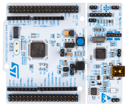
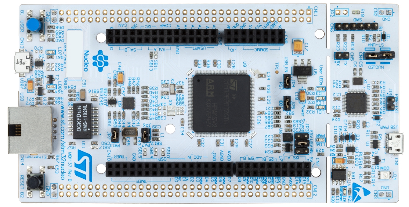
STM32 Nucleo boards#
These boards come with a cheap price and an integrated ST-LINK debugger. The advantages of this Nucleo board line is to have access directly to all GPIOs, and to have compliant Arduino connector. Many users who are familiar with Arduino like to use Nucleo boards, because they can keep using these STM32 boards as an Arduino.
Starter boards can be:
- Nucleo-F103RB
- Nucleo-F401RE/F411RE
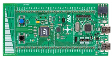
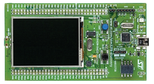
STM32 Discovery kits#
This line of board allows either for beginner or for experienced users to get started on new projects.
These boards are cheap, and have complete solutions for demonstrating the capabilities of the devices. Some boards come with many peripherals such as LCD, MEM sensors, touchpad. They also have integrated ST-LINK debugger/ programmer.
Starter boards can be:
- STM32F072-Discovery
- STM32F429-Discovery
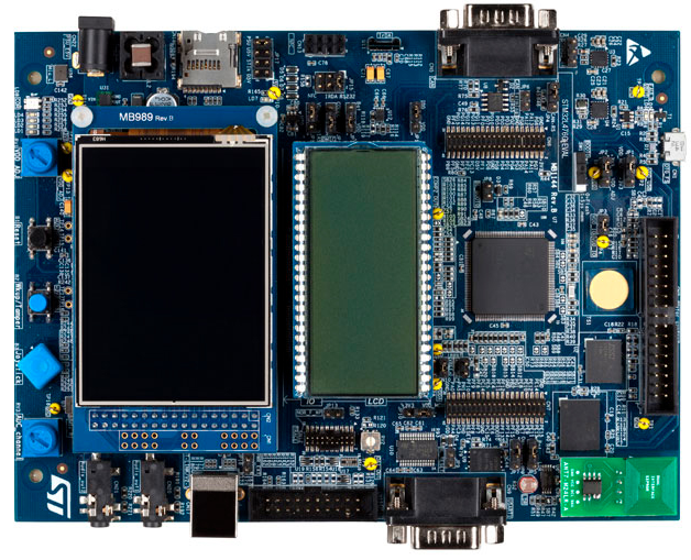
Evaluation board#
The STM32 Evaluation boards have been designed as a complete demonstration and development platform for the STM32 MCUs and MPUs. They are meant to be used to execute a comprehensive evaluation of ST Microelectronics solutions.
These boards have integrated ST-LINK debugger/ programmer. They carry external circuitry, such as transceivers, sensors, memory interfaces, displays and many more. The evaluation boards can be considered as a reference design for application development.
Starter boards can be:
- STM32L476-EVAL
- STM32F407-EVAL

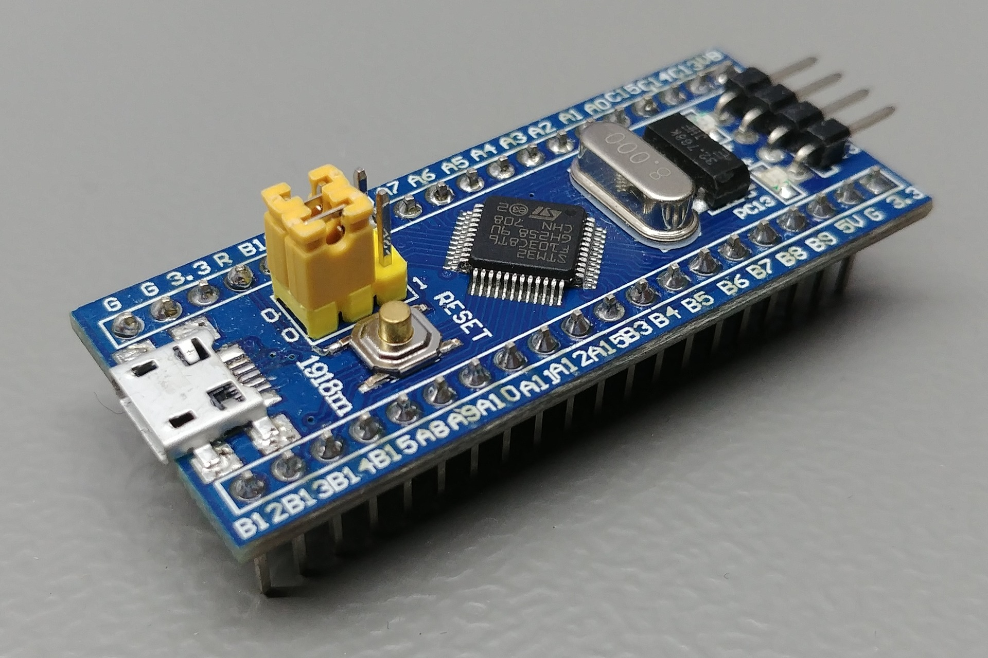
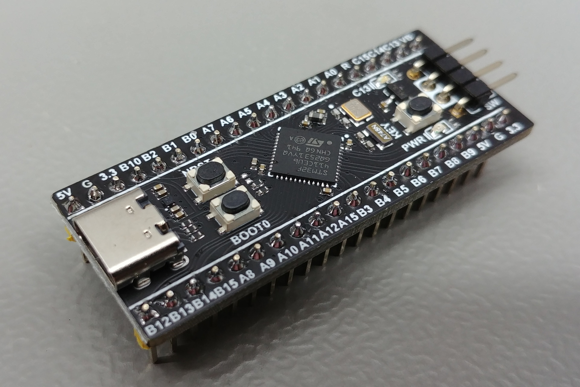
Custom board#
Many users still find that the price of original boards is still high. There are many clones which use either authorized MCUs or even fake ones, with reduced peripherals. They are usually customized as different starter boards in small size and exposed just USB and debugging pins.
The popular custom boards are “Blue Pills” STM32F103, and “Black Pills” STM32F4x1. They are cheap and have many exposed pins. There is no debugger or programmer in these custom boards. Users have to use an external one, such as ST-LINK or J-LINK.
Power conflict
On a custom board, there may be no power protection circuit added, therefore, do not connect 3.3 V power pin of the debugger to the board if the on-board USB port is plugged because the USB port already powers the board using 5 V line.
Counterfeit chip
There are counterfeit chips on the market that are blocked to work with ST-Link/ J-Link to flash and debug. Please make sure to not buy them, even there is a method to workaround with OpenOCD Update: new version of OpenOCD doesn't work with counterfeit chips anymore.
Programmer & Debugger#
Programmer is used to write application code into MCU. It can read the application and make a copy of the firmware.
Debugger is used to read CPU registers, memory, and logging data to help developers see how application runs. It can halt the CPU too. In monitoring mode, it lets CPU run and read memory in background through some special channels to gather information of application and system in real-time.
ST-LINK#
All official boards from ST have integrated ST-Link debugger / programmer in version 2 or 3. They work on a Serial Wire Debug (SWD) interface. ST-Link comes with good performance and some extra feature such as Serial Wire Output (SWO), Virtual COM port, Mass-storage for drag-and-drop programming.
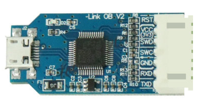
On custom boards, there is no on-board debugger, so that an external debugger is needed. There are both original and clone version in the market.
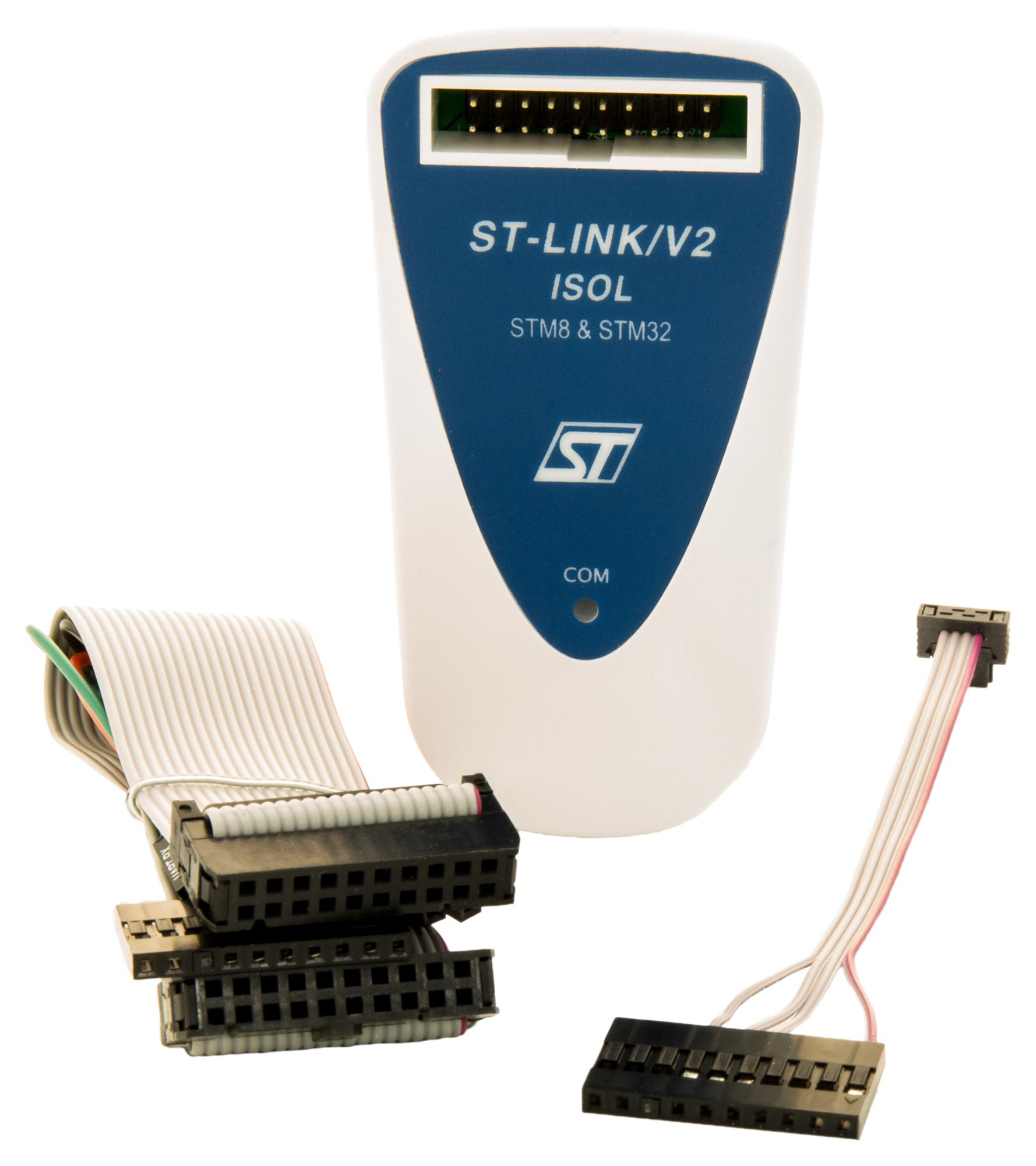
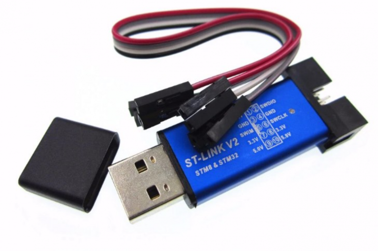
Missing SWO pin on ST-LINK clones
Many ST-LINK clones only expose SWD interface (SWCLK and SWDIO). The pin for SWO is not exposed. There is a quick fix for this problem: wire the PA10 of the on-board STM32 chip to a pin on the header, read more in Export SWO pin note.
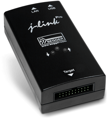
J-LINK#
One of a popular (and expensive) debugger manufacturer is SEGGER. They provide many tools for embedded systems. Their J-Link is quite expensive but comes with a lot of high performance features beside standard ones in ST-LINK, such as Real-time logging, system view, profiling.
There are also cloned J-Link devices which are actually an STM32F0 MCU running a SEGGER firmware but have limitation in features due to missing hardware component and license.
One interesting thing is SEGGER provides a tool to convert on-board ST-LINK/V2 to a J-LINK OB model with some limitations. You still are able to convert it back to original ST-Link debugger. After reverting to ST-Link, it’s recommended to re-flash ST-Link firmware if you run into any problem.
Power Supplier#
There are many ways to power the board. Always check the Voltage and the Maximum Current of the power source.
During the development, the board should be powered through the debugger which connects to PC via a USB port. If the on-board USB port is connected to power source, do not connect the power pin from the debugger.
In the final production, the board will run without a debugger connected to a host PC, the power can be connected to the USB port or the power pins directly either on 5 V or 3.3 V pin.
A portable power source can be a Power bank, or a Li-Po battery. Also keep in mind that if the board would occasionally go to sleep state and the consumption current drops below 50 – 70 mA, many power banks would drop the supply, so the system will shut down catastrophically.
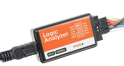
Logic Analyzer (optional)#
A Logic Analyzer can capture (and display) multiple signals on a system. The output can be visualized in timing diagrams, and then analyzed or decoded to get detailed information about the signal or the protocol and data.
There are small portable Logic Analyzers which just do capturing data, and then the captured data is transferred to a host PC via USB. Finally, the data is visualized by an application.
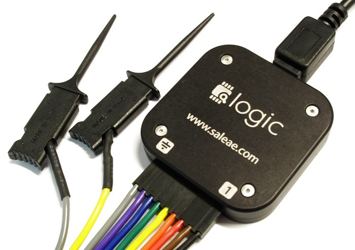
The bandwidth of data collection heavily depends on the USB Host Controller on the the host PC. Modern laptops have only one USB 3.0 Host Controller and bandwidth is shared to many USB Devices, that sigifincantly reduce avaiable bandwidth reserved for your Logic Analyser’s USB port.