Stack Memory
Stack Memory is part of the main memory reserved for the temporary storage of data (transient data), mainly used in function call, interrupt/exception handling. The ARM Cortex-M processor uses a full descending stack model. The processor also implements two stacks, the main stack and the process stack, with a pointer for each held in independent registers
Last update: 2022-06-04
Table of Content
STM32-Tutorials F411RE_Stack.zip
Stack#
Stack Memory is part of the main memory reserved for the temporary storage of data (transient data), mainly used in function call, interrupt/exception handling.
Stack Memory is accessed in Last In First Out LIFO manner. The stack can be accessed using PUSH, POP or memory instructions such as LDR, STR.
The stack is traced by the Stack Pointer (SP), and is used to save below information:
- Temporary storage for processor register values
- Temporary storage for local variables of functions
- Save the context of the current executing code before moving to exception/ interrupt handing routine

Processor Stacks#
The ARM Cortex-M processor uses a full descending stack. This means the stack pointer indicates the last stacked item on the stack memory. When the processor pushes a new item onto the stack, it decrements the stack pointer and then writes the item to the new memory location. The processor implements two stacks, the main stack and the process stack, with independent copies of the stack pointer.
The Stack Pointer (SP) is register R13. In Thread mode, bit[1] of the CONTROL register indicates the stack pointer to use:
0: Main Stack Pointer (MSP). This is the default after reset, used for all exception/ interrupt handler and also for code running in thread mode.1: Process Stack Pointer (PSP). This alternative stack is only can be used in thread mode. It is usually used for application task in embedded systems and OS
On reset, the processor loads the MSP with the value from address 0x00000000.
| Processor mode | Code execute | Access level | Stack used |
|---|---|---|---|
| Thread | Applications | Privileged or unprivileged | Main stack or process stack |
| Handler | Exception handlers | Always privileged | Main stack |
Stack placement#
In ARM projects based on ARM CMSIS, the linker decides to place Stack at the end of RAM.
Let check the linker file STM32F411RETX_FLASH.ld:
/* Highest address of the user mode stack */
_estack = ORIGIN(RAM) + LENGTH(RAM); /* end of "RAM" Ram type memory */

_Min_Heap_Size = 0x200; /* required amount of heap */
_Min_Stack_Size = 0x400; /* required amount of stack */

/* Memories definition */
MEMORY
{
  RAM    (xrw)    : ORIGIN = 0x20000000,   LENGTH = 128K
  FLASH    (rx)    : ORIGIN = 0x8000000,   LENGTH = 512K
}
On reset, the processor loads the MSP with the value from address 0x00000000. At that initial address, the Interrupt Vector Table must be there.
The startup code in startup_stm32f411retx.s defines the isr_vector as below:
.section .isr_vector,"a",%progbits
  .type g_pfnVectors, %object
  .size g_pfnVectors, .-g_pfnVectors

g_pfnVectors:
  .word _estack
  .word Reset_Handler
  .word NMI_Handler
...
with the value of _estack at the 0x00000000 which is declared in the linker script:
/* Sections */
SECTIONS
{
  /* The startup code into "FLASH" Rom type memory */
  .isr_vector :
  {
    . = ALIGN(4);
    KEEP(*(.isr_vector)) /* Startup code */
    . = ALIGN(4);
  } >FLASH
...

Prologue and Epilogue sequences#
In assembly language programming, the function prologue is a few lines of code at the beginning of a function, which prepare the stack and registers for use within the function. Similarly, the function epilogue appears at the end of the function, and restores the stack and registers to the state they were in before the function was called.
Prologue
A function prologue typically does the following actions if the architecture has a base pointer (also known as frame pointer) and a stack pointer:
- Pushes current base pointer onto the stack, so it can be restored later.
- Value of base pointer is set to the address of stack pointer (which is pointed to the top of the stack) so that the base pointer will point to the top of the stack.
- Moves the stack pointer further by decreasing or increasing its value, depending on whether the stack grows down or up. On x86, the stack pointer is decreased to make room for the function’s local variables.
Example:
push    {r7}                            ; Save frame pointer
sub     sp, #20             ; Reserve 20 bytes
add     r7, sp, #0          ; Set frame pointer to new stack pointer
str     r0, [r7, #12]       ; Save params on R0-R3 to stack
str     r1, [r7, #8]
str     r2, [r7, #4]
str     r3, [r7, #0]
Epilogue
Function epilogue reverses the actions of the function prologue and returns control to the calling function. It typically does the following actions (this procedure may differ from one architecture to another):
- Drop the stack pointer to the current base pointer, so room reserved in the prologue for local variables is freed.
- Pops the base pointer off the stack, so it is restored to its value before the prologue.
- Returns to the calling function, by popping the previous frame’s program counter off the stack and jumping to it.
Example:
adds    r7, #20             ; Return back to last stack pointer
mov     sp, r7
ldr.w   r7, [sp], #4        ; Get last frame pointer
bx      lr                  ; Exit function by brach and execute saved instruction in LR
Example#
In this example, we will create 2 Stack Regions and assign them to MSP and PSP.
Step 0: Create a new project
You should create a bare-metal project which just has a few files including a linker and a main.
Step 1: Define Stack Start Address
The stack model is that Main Stack and Process Stack are a half of allocated stack space. By default, after reset, the processor uses the Main Stack, therefore, Main Stack is located at the start of Stack region.

In the linker script STM32F411RETX_FLASH.ld, define 2 new symbols _msp_stack and _psp_stack:
/* Highest address of the user mode stack */
_estack = ORIGIN(RAM) + LENGTH(RAM); /* end of "RAM" Ram type memory */

_Min_Heap_Size = 0x200; /* required amount of heap */
_Min_Stack_Size = 0x400; /* required amount of stack */

_msp_stack = _estack;
_psp_stack = _estack - _Min_Stack_Size / 2;
Step 2: Demo program to change Stack to PSP
int add(int a, int b, int c, int d) {
return a+b+c+d;
}
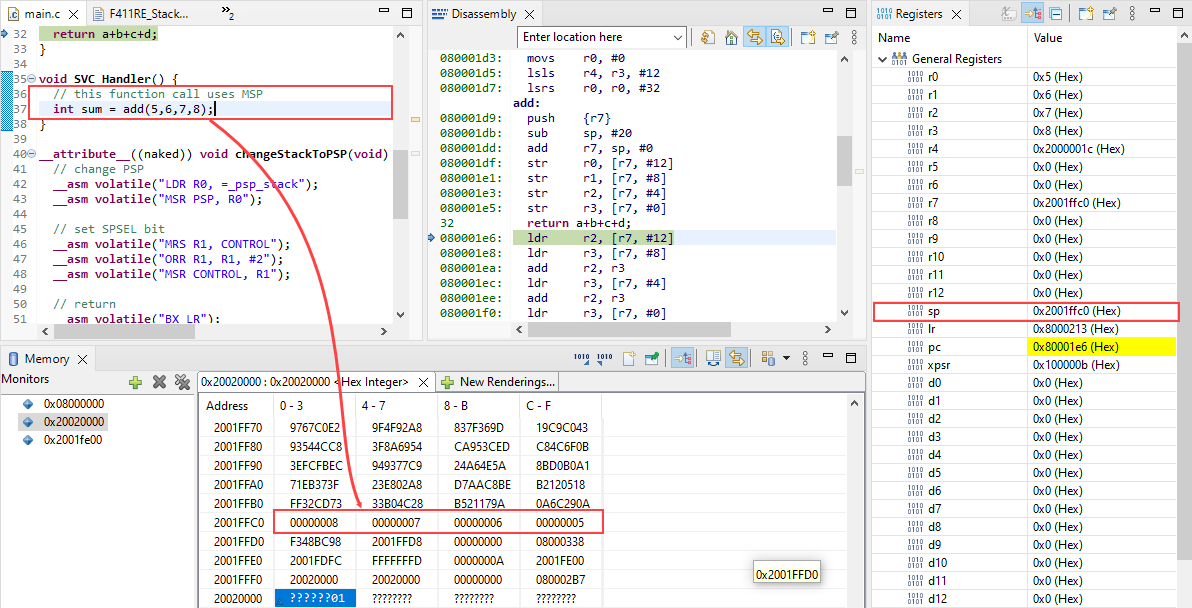
void SVC_Handler() {
// this function call uses MSP
int sum = add(5,6,7,8);
}
__attribute__((naked)) void changeStackToPSP(void) {
// change PSP
__asm volatile("LDR R0, =_psp_stack");
__asm volatile("MSR PSP, R0");
// set SPSEL bit
__asm volatile("MRS R1, CONTROL");
__asm volatile("ORR R1, R1, #2");
__asm volatile("MSR CONTROL, R1");
// return
__asm volatile("BX LR");
}
void callSVC() {
__asm volatile("SVC #0");
}
int main(void)
{
changeStackToPSP();
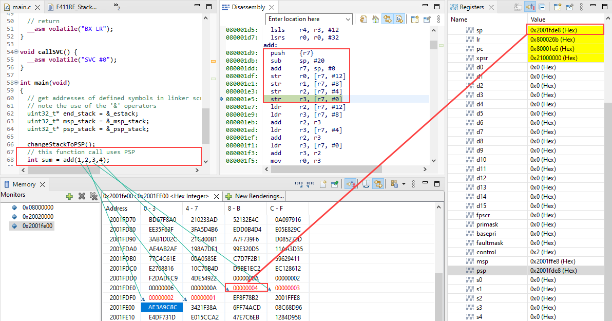
// this function call uses PSP
int sum = add(1,2,3,4);
// trigger SVC will force to use MSP
callSVC();
/* Loop forever */
for(;;);
}
Step 4: At reset
You have to place a breakpoint right at the Reset_Handler function which is the first instruction loaded into PC.
Right after CPU reset:
- The
MSPregister is loaded from the address0x00000000in System Memory (alias to0x08000000in Flash) which has_estackvalue. - The
PCregister then is loaded with the value at the address0x00000004which is the address ofReset_Handler(added 1 to set the Thumb bit).
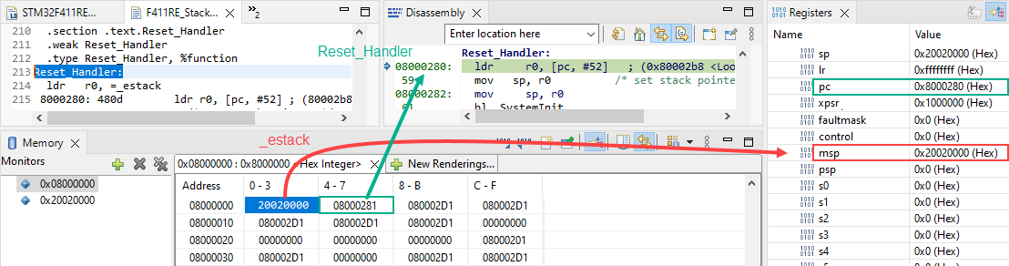
_estack and Reset_Handler are loaded to MSP and PC at reset
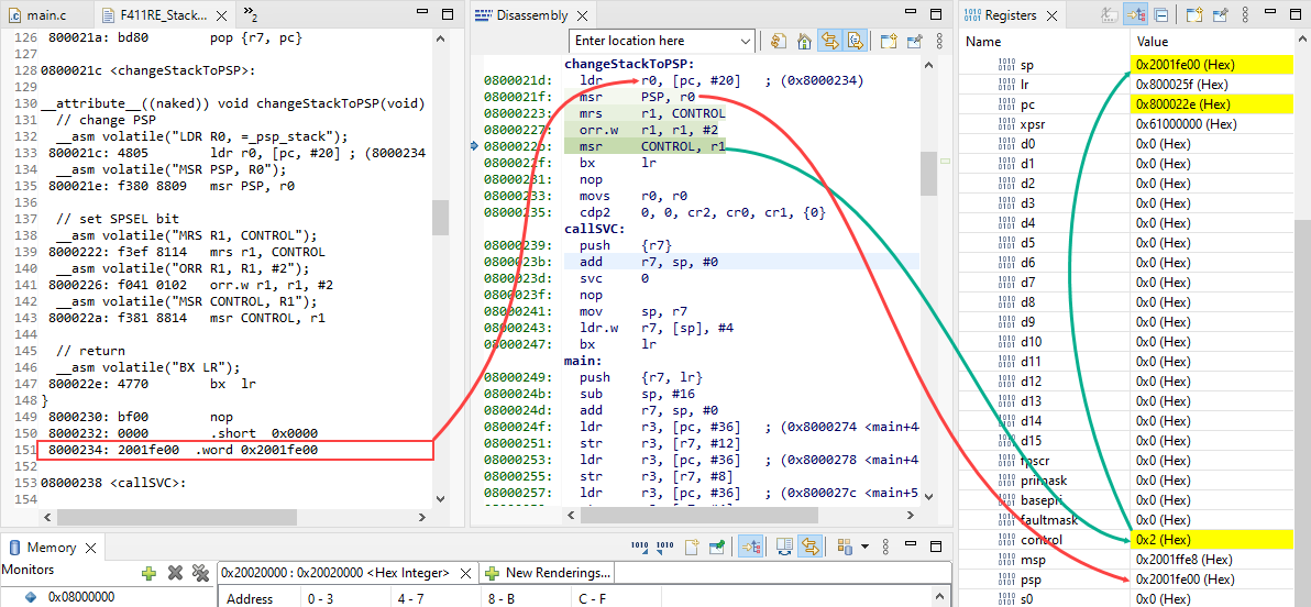
Step 5: Application changes to use PSP
To change to PSP stack, we have to write a special function that set a new value to PSP regsiter, and set a bit in CONTROL register.
__attribute__((naked)) is used to tell compiler that this function is embedded assembly function and compiler does not generate prologue and epilogue sequences for it. The compiler only supports basic __asm statements in __attribute__((naked)) functions.
Note that:
- The
_psp_stacksymbol is defined in the linker script. - Manually return from a naked function (no epilogue) using assembly instruction
BX LR
__attribute__((naked)) void changeStackToPSP(void) {
  // change PSP
  __asm volatile("LDR R0, =_psp_stack");
  __asm volatile("MSR PSP, R0");

  // set SPSEL bit
  __asm volatile("MRS R1, CONTROL");
  __asm volatile("ORR R1, R1, #2");
  __asm volatile("MSR CONTROL, R1");

  // return
  __asm volatile("BX LR");
}
Step 6: Exception Handler uses MSP
When CPU sees an SVC call, it automatically changes to MSP Stack by setting SP to MSP.
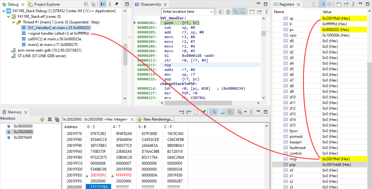
During an exception/ interrupt handler, MSP is used.
If we do not clear the SPSEL in the CONTROL register, the SP register will be switch back to PSP after returning from the exception/ interrupt handler.
Procedure Call Standard for Arm Architecture (AAPCS)#
A Procedure Call Standard or Calling Convention defines how different compilation units, even when compiled by different compilers, can work together. It defines how parameters are passed from one function to another, which registers and other program states must be preserved by caller a callee and what might be altered by the callee. The procedure call standard is one in a set of standards, which define the application binary interface (ABI) a compilation unit has to respect.
- Parameters and Arguments
-
- A parameter is a variable name and type, which is part of the declaration of the function
- An argument, on the other side, is the actual value passed into a function
- Caller-saved and Callee-saved registers
-
- The general-purpose registers
R0-R3are used to pass arguments to a function and also return values. They are not needed to be preserved by the callee, they are caller-saved. - The registers
R4-R8,R10andR11are used to hold local variables within a function. A caller can expect them to be unchanged, when the called function returns: They are callee-saved.
- The general-purpose registers
- Passing arguments
-
The arguments are bound to registers, which is used to pass the argument to the function. When all caller-saved registers (
R0toR3) are bound to arguments, the stack is used to pass all arguments left:int add(int a, int b, int c, int d, int e) { return a+b+c+d+e; } int main() { int sum = add(1,2,3,4,5); }xxxxxxx<main>: 8000266: 2305 movs r3, #5 ; 8000268: 9300 str r3, [sp, #0] ; save arg 5 to stack 800026a: 2304 movs r3, #4 ; save arg 4 to R3 800026c: 2203 movs r2, #3 ; save arg 3 to R2 800026e: 2102 movs r1, #2 ; save arg 2 to R1 8000270: 2001 movs r0, #1 ; save arg 1 to R0 8000272: f7ff ffb1 bl 80001d8 <add> ; call to function ... 080001d8 <add>: 80001d8: b480 push {r7} ; save frame pointer 80001da: b085 sub sp, #20 ; reserve 20 bytes on stack 80001dc: af00 add r7, sp, #0 ; set new frame pointer 80001de: 60f8 str r0, [r7, #12] ; save arg 1 to stack 80001e0: 60b9 str r1, [r7, #8] ; save arg 2 to stack 80001e2: 607a str r2, [r7, #4] ; save arg 3 to stack 80001e4: 603b str r3, [r7, #0] ; save arg 4 to stack 80001e6: 68fa ldr r2, [r7, #12] ; get arg 1 from stack 80001e8: 68bb ldr r3, [r7, #8] ; get arg 2 from stack 80001ea: 441a add r2, r3 ; sum += arg 1 + arg 2 80001ec: 687b ldr r3, [r7, #4] ; get arg 3 from stack 80001ee: 441a add r2, r3 ; sum += arg 3 80001f0: 683b ldr r3, [r7, #0] ; get arg 4 from stack 80001f2: 441a add r2, r3 ; sum += arg 4 80001f4: 69bb ldr r3, [r7, #24] ; get arg 5 from stack 80001f6: 4413 add r3, r2 ; sum += arg 5 80001f8: 4618 mov r0, r3 ; save sum to r0 as return value 80001fa: 3714 adds r7, #20 ; restore frame pointer 80001fc: 46bd mov sp, r7 ; restore stack pointer 80001fe: f85d 7b04 ldr.w r7, [sp], #4 ; get saved frame pointer, pop back stack pointer 8000202: 4770 bx lr ; return ...
Arguments on stack during function call
Context Saving on Stack#
When application is running, if there is any exception/ interrupt raised, the processor will do a special procedure called “Context Saving”.
Context saving allows the current executing application flow is saved and then restored because all registers would have the same values as when the interrupt started.
This context saving also be used to switch tasks which is used in OS.

When the processor takes an exception, unless the exception is a tail-chained or a late-arriving exception, the processor pushes information onto the current stack. This operation is referred as stacking and the structure of eight data words is referred as stack frame.
When using floating-point routines, the Cortex-M4 processor automatically stacks the architected floating-point state on exception entry.
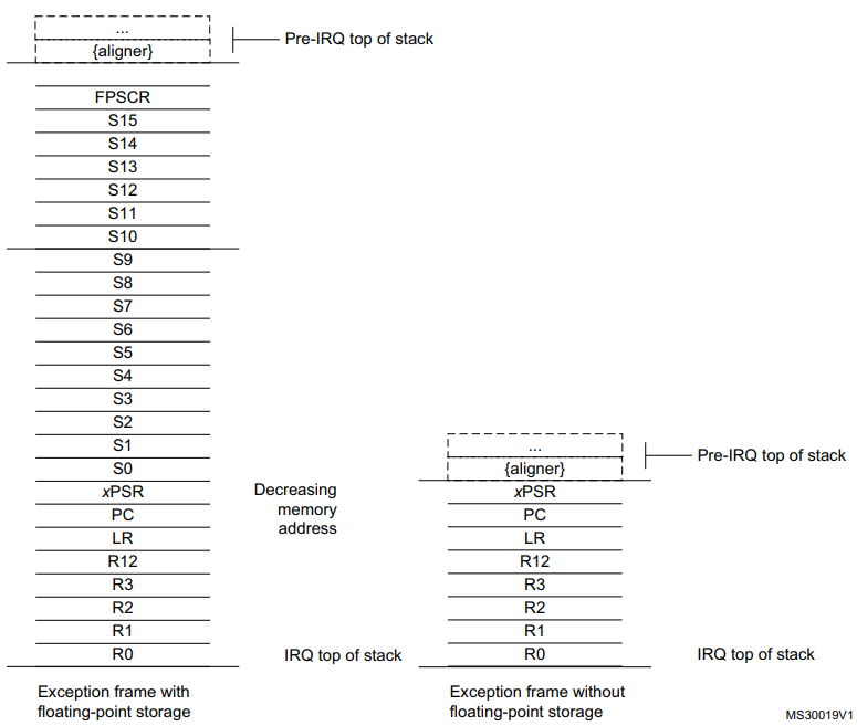
The stack frame includes the return address. This is the address of the next instruction in the interrupted program. This value is restored to the PC at exception return so that the interrupted program resumes.