IMU Module using DK-20789
Last update: 2022-05-07
Table of Content
Example project#
The development board DK-20789 comes with some example projects which are very good base to start with. The project is NOT documented, and some parts are close-source.
Documents#
-
Firstly, check the ICM-20789 Datasheet.
-
Have a quick look of different development kits which can be found in SmartMotion Platform Introduction and Training.
-
The SmartMotion Hardware User Guide shows the notes and schematics of development kits.
Download#
Register an account and download Embedded Motion Drivers (eMD) from the Download center.
There are 2 versions:
-
Without Digital Motion Processor, named
eMD-SmartMotion_ICM207xx:Motion processing algorithms will be run on the host processor. The host process reads all raw data and the process them. The prebuilt TDK algorithm and math libraries is not open source. It is compiled and provided as library files
libAlgoInvn.aandlibMLMath.a.Non-DMP version exposes below raw sensor’s data:
SENSOR_ACCELEROMETER(id: 1)SENSOR_GYROSCOPE(id: 4)SENSOR_GRAVITY(id: 9)SENSOR_LINEAR_ACCELERATION(id: 10)SENSOR_GAME_ROTATION_VECTOR(id: 15)SENSOR_UNCAL_GYROSCOPE(id: 16)SENSOR_RAW_ACCELEROMETER(id: 32)SENSOR_RAW_GYROSCOPE(id: 33)SENSOR_CUSTOM_PRESSURE(id: 36)
-
With Digital Motion Processor enabled, named
eMD-SmartMotion-ICM20789-20689-DMP:Motion processing algorithms will be run on sensor itself. The host process reads all processed data when DMP sends an interrupt status. The firmware of the DMP processor is also prebuilt. It’s stored in the binary array defined in
icm20789_img.dmp3.h. This array will be uploaded to the DMP Processor when the main application runs.DMP version exposes below processed sensor’s data:
SENSOR_GYROSCOPE(id: 4)SENSOR_GAME_ROTATION_VECTOR(id: 15)SENSOR_UNCAL_GYROSCOPE(id: 16)SENSOR_RAW_ACCELEROMETER(id: 32)SENSOR_RAW_GYROSCOPE(id: 33)SENSOR_CUSTOM_PRESSURE(id: 36)
The projects which are used on the DK-20789 board are built with Atmel Studio (newly changed to Microchip Studio). Download the Atmel Studio at the Microchip download page for AVR and SAM devices.
After download the eMD SmartMotion ICM-20789 DMP project, open the solution file EMD-G55-ICM207*.atsln to start the project.
Understanding the example projects#
The example projects come with some components of InvenSense, such as Dynamic Protocol Adapter (with Data and Transport layers), and prebuilt algorithms. I haven’t found any document about InvenSense’s Dynamic Protocol.
The application initializes all the components, and then finally does a loop to:
- read bytes from UART to process commands in Dynamic Protocol Adapter
- poll sensor’s data when sensor sends an interrupt
- call the algorithms to process sensor’s data
- converted processed sensor’s data to messages for Dynamic Protocol Adapter to send through UART
Dynamic Protocol Adapter is working well with a provided example host’s application named sensor_cli. But this program is close-source, and no document of Dynamic Protocol Adapter is found, Dynamic Protocol Adapter layer should be removed in customized projects.
Let’s quickly review the application code.
-
UART ports are set up in the function
configure_console(). The debug port is through theFLEXCOM7peripheral, at 921600 bps. The main console is through theFLEXCOM0peripheral at 2000000 bps. The console UART also enables interruption for receiving readyUS_IER_RXRDY. -
Sensors are set up in the function
icm207xx_sensor_setup()and the initial configurations are set inicm207xx_sensor_configuration()function. By default, the Accelerator sensor at ± 4000 mg, the Gyroscope sensor at ± 2000 dps, and the Temperature sensors are enabled, and the output rate is 50 Hz. -
The application attaches the console UART to the Dynamic Protocol Adapter with
DynProTransportUart_init()andDynProtocol_init()which set callbacks to handle data in and out through the console UART port. -
The algorithms are then initialized and configured by the
algorithms_init()andalgorithms_configure_odr(). Note the output data rate of the sensor should be matched with algorithm’s. -
At the boot time, all sensor output types are turned on. The variable
enabled_sensor_maskis used as the flags to set which output types are enabled. Here is the list of sensor output types:- Raw Accelerator data
- Raw Gyroscope data
- Calibrated Accelerator data
- Calibrated Gyroscope data
- Un-calibrated Gyroscope data
- Game Rotation Vector
-
Two tasks
commandHandlerTaskandblinkerLedTaskare initialized, and started in the InvenSense’s scheduler (no document about it, though its code, this not an RTOS, because it schedules tasks and run the selected task in the main loop). -
In the main loop:
- the scheduler will check the task which will be executed and runs it
- call to
Icm207xx_data_poll()function to read sensor’s data when the interrupt flagirq_from_deviceis set - call to
sensor_event()to forward sensor’s data to the Dynamic Protocol to encode the message and transmit it to the host

Send raw sensor’s data#
The example project needs to be modified to adapt to new system:
-
Start with Non-DMP version from
eMD-SmartMotion_ICM207xx_1.0.5. -
Set jump
J1at pin 5-6 to select power from FTDI USB port -
Configure project and board to use SPI protocol which provides higher data rate.
- Set
#define USE_SPI_NOT_I2C 1in filesystem.h - Remove jumps on
J2to use SPI between ATSAMG55 and ICM207xx
- Set
-
Set jump
J3on pin 1-2 and 3-4 to use UART over FTDI USB port -
Disable reading pressure sensor save CPU usage
- In
main.c, remove all defines and function calls related to pressure sensor:invpres_serif,inv_invpres_setup,irq_start_pressure_capture
- In
-
Remove Dynamic protocol to and Scheduler to work with raw data from sensor
- In
main.c, remove all function calls to set up protocol, such asDynProTransportUart_init,DynProtocol_init - In
main.c, remove all function calls to scheduler, such asInvScheduler_init,InvScheduler_initTask,InvScheduler_startTask - In
system.c, remove code inside the functionsTC0_HandlerandSysTick_Handler. -
In
main.c, set sensor mask to get calibrated Accelerometerenabled_sensor_mask |= (1 << SENSOR_ACC); // Calibrated ACCELEROMETER enabled_sensor_mask |= (1 << SENSOR_GYR); // Calibrated GYROSCOPE
- In
-
Send raw sensor’s event data to UART
-
In
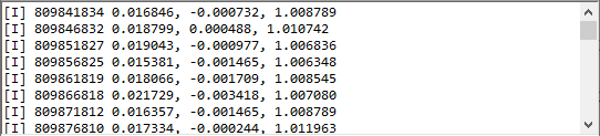
sensor.c, at the beginning of the functionsensor_event(), call to UART write function:void sensor_event(const inv_sensor_event_t * event, void * arg) { usart_serial_write_packet(CONF_UART, (uint8_t*)event, sizeof(inv_sensor_event_t)); ioport_toggle_pin_level(LED_0_PIN); }
-
-
Remove timestamp in
inv_sensor_event_t, addsyncBytesto mark the start of event struct, and shorten the struct definition to get a smaller sizetypedef struct inv_sensor_event { unsigned int syncBytes; /**< 0x55AA55AA */ unsigned int sensor; /**< sensor type */ union { struct { float vect[3]; /**< x,y,z vector data */ float bias[3]; /**< x,y,z bias vector data */ uint8_t accuracy_flag; /**< accuracy flag */ } acc; /**< 3d accelerometer data in g */ struct { float vect[3]; /**< x,y,z vector data */ float bias[3]; /**< x,y,z bias vector data (for uncal sensor variant) */ uint8_t accuracy_flag; /**< accuracy flag */ } gyr; /**< 3d gyroscope data in deg/s */ struct { float quat[4]; /**< w,x,y,z quaternion data */ float accuracy; /**< heading accuracy in deg */ uint8_t accuracy_flag; /**< accuracy flag specific for GRV*/ } quaternion; /**< quaternion data */ struct { int32_t vect[3]; /**< x,y,z vector data */ uint32_t fsr; /**< full scale range */ } raw3d; /**< 3d raw acc, mag or gyr*/ } data; /**< sensor data */ } inv_sensor_event_t;The sync bytes must be assigned when a new event is created, such as in
notify_eventfunction:void notify_event(uint64_t timestamp) { inv_sensor_event_t event; memset(&event, 0, sizeof(event)); event.syncBytes = 0x55AA55AA; ... }At this step, the main loop of sensor data handler is reduced as below
main() { while(1) { if(irq_from_device) { Icm207xx_data_poll() { inv_icm207xx_poll_fifo_data() algorithms_process() notify_event() { for each enabled sensor in enabled_sensor_mask { new inv_sensor_event_t sensor_event() { usart_serial_write_packet(); ioport_toggle_pin_level(); ... -
Change output rate
- In
algo_eapi.h, set the definitionDEFAULT_ODR_USto5000(ms) to get 200 Hz output rate - The bit rate of UART port
CONF_UART_BAUDRATEalso need to be increased to921600bps inconf_uart_serial.h
- In
Mismatched timestamp for Accelerator and Gyroscope data
Accelerator and Gyroscope should be the same timestamp, but DK-20789 sends those data in 2 different packages.
Todo:
- Fuse Accelerator and Gyroscope data before sending to synchronize timestamp
Handshake protocol#
Due to the output rate is 200 Hz, the receiver buffer can be overflown if the messages keep coming at startup. Therefore, it is better to keep IMU output off, and only turns it on when receiver is ready to handle data.
DK-20789 board reads from the console UART to check the commands:
0xAA 0x55 0xAA 0x55 0x00to turn off output0xAA 0x55 0xAA 0x55 0x5Ato turn ON output
This method is implemented in the function console_uart_irq_handler().
Appendix#
Digital Motion Processor
The embedded Digital Motion Processor (DMP) offloads computation of motion processing algorithms from the host processor. The DMP acquires data from the accelerometer and gyroscope, processes the data, and the results can be read from the FIFO.
The DMP has access to one of the external pins, which can be used for generating interrupts. The purpose of the DMP is to offload both timing requirements and processing power from the host processor.
Typically, motion processing algorithms should be run at a high rate, often around 200 Hz to provide accurate results with low latency. This is required even if the application updates at a much lower rate; for example, a low power user interface may update as slowly as 5 Hz, but the motion processing should still run at 200 Hz.
The DMP can be used to minimize power, simplify timing, simplify the software architecture, and save valuable MIPS on the host processor for use in applications. DMP operation is possible in low-power gyroscope and low-power accelerometer modes.