Diagnostic Camera on I2C Bus
When the camera is not detected, it could happen due to a loosen cable or any hardware failure. There is a technique to scan devices on an I2C bus which can be used to do a quick check on hardware problems of a Pi's camera module.
Last update: 2022-05-07
Table of Content
Address of Camera modules
Scan on the I2C Bus 0, the camera module will response on two addresses 0x10 (camera sensor) and 0x64 (camera board).
Missing one of two above addresses means that there is an hardware issue happened.
Hardware check#
Run the command:
vcgencmd get_camera
which should print out supported=1 detected=1 with a normal working camera.
If the output shows detected=0, check the ribbon cable first. If other camera module still works after swapping with the problem one, then do a hardware check from software interface as described below.
Software check#
An interesting topic: Camera not detected despite being plugged in on the official Raspberry forum shows a method to check the connection of the camera board and the camera sensor on an I2C interface.
Install I2C tools#
Run below command to install I2C tools:
sudo apt install -y i2c-tools
This package contains a set of I2C tools for Linux: a bus probing tool, a chip dumper, register-level access helpers, EEPROM decoding scripts, and more.
i2cdetect       # detect I2C chips
i2cdump         # examine I2C registers
i2cget          # read from I2C/SMBus chip registers
i2cset          # set I2C registers
i2ctransfer     # send user-defined I2C messages in one transfer
Load I2C driver#
It is able to permanently enable the I2C interface by running sudo raspi-config and enable I2C setting, or by adding i2c-dev declaration in the file /etc/modules.
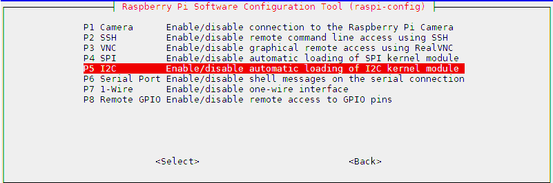
raspi-config
However, for a quick check, just need to load driver temporarily:
sudo modprobe i2c-dev
Configure GPIO#
GPIO Pinout number
Please look at PI GPIO document for more information about setting GPIOs.
Note that GPIO number is defined in BCM2835 ARM processor, not the number printed on the Pi boards. Read more at BCM2835 Peripherals.
Use raspi-gpio get to read the current status of GPIOs.
-
Change GPIO0 and GPIO1 to input (by default they are set to SDA0 and SCL0):
raspi-gpio set 0 ip raspi-gpio set 1 ip -
Change the function of GPIO28, GPIO29 to I2C pins out SDA0 and SCL0 by setting Alternate Function 0 (A0) on those pins.
raspi-gpio set 28 a0 raspi-gpio set 29 a0 -
Power on Camera by setting High on output pin GPIO44 and GPIO45
raspi-gpio set 44 dh
raspi-gpio set 40 dh
Scan I2C bus#
Run i2cdetect on I2C BUS 0 at /dev/i2c-0:
i2cdetect 0
press Y to continue, and it should print out some numbers, for example:
     0  1  2  3  4  5  6  7  8  9  a  b  c  d  e  f
00:          -- -- -- -- -- -- -- -- -- -- -- -- --
10: 10 -- -- -- -- -- -- -- -- -- -- -- -- -- -- --
20: -- -- -- -- -- -- -- -- -- -- -- -- -- -- -- --
30: -- -- -- -- -- -- -- -- -- -- -- -- -- -- -- --
40: -- -- -- -- -- -- -- -- -- -- -- -- -- -- -- --
50: -- -- -- -- -- -- -- -- -- -- -- -- -- -- -- --
60: -- -- -- -- 64 -- -- -- -- -- -- -- -- -- -- --
70: -- -- -- -- -- -- -- --
Consider that i2cdetect tries to ping every address on a bus and reports whether an address responds. If any number shows up in report, it means there is a working device at that address.
Camera’s I2C addresses
If having 0x64, the camera board is connected properly, there is no problem with cable and main connectors on Pi board and camera board.
If having 0x10, it means the camera sensor has responded. there is no problem with sensor and sensor connection (a small cable between camera board and camera sensor).