Exception and Interrupt
The current executing application on a processor can be interrupted by either internal system exception or external interrupt. Whenever the processor meets an exception or interrupt, the core will stop the application code, change its mode to "Handler mode" to process that event. Cortex-M processors have 15 system Exceptions and 240 Interrupts.
Last update: 2022-05-16
Table of Content
Exception model#
The current executing application on a processor can be interrupted by either internal system exception or external interrupt. Whenever the processor meets an exception or interrupt, the core will stop the application code, change its mode to “Handler mode” to process that event.
Cortex-M processors have 15 system Exceptions and 240 Interrupts.
Exception states#
- Inactive
- The exception is not active and not pending.
- Pending
- The exception is waiting to be serviced by the processor. An interrupt request from a peripheral or from software can change the state of the corresponding interrupt to pending.
- Active
- An exception that is being serviced by the processor but has not completed.
Note: An exception handler can interrupt the execution of another exception handler. In this case both exceptions are in the active state. - Active and pending
- The exception is being serviced by the processor and there is a pending exception from the same source
Exception types#
Whenever an interrupt happens, the processor stops the current code, and handle the interrupt by running an Interrupt Service Routines (ISR) which is located in a pre-defined table called Vector Interrupt Table (VIC).
The Vector Interrupt Table defines different types with priority of handling order as below:
| Exception Number | IRQ Number | Exception Type | Priority | Function |
|---|---|---|---|---|
| 1 | -15 | Reset | -3, the highest | Reset |
| 2 | -14 | NMI | -2 | Non-Maskable Interrupt |
| 3 | -13 | Hard Fault | -1 | All faults that hang the processor |
| 4 | -12 | Memory Fault | Configurable | Memory issue |
| 5 | -11 | Bus Fault | Configurable | Data Bus issue |
| 6 | -10 | Usage Fault | Configurable | Instruction/State/Access issue |
| 7 ~ 10 | Reserved | — | Reserved | |
| 11 | -5 | SVCall | Configurable | System Service Call when call SVC instruction |
| 12 | Debug | Configurable | Debug monitor (via SWD) | |
| 13 | Reserved | — | Reserved | |
| 14 | -2 | PendSV | Configurable | For context switching in an OS |
| 15 | -1 | SysTick | Configurable | System Timer |
| 16 ~ 255 | 0~239 | Interrupt (IRQ) | Configurable | Interrupt Request by a peripheral, or software request |
IRQ Number
To simplify the software layer, the CMSIS only uses IRQ numbers and therefore uses negative values for exceptions other than interrupts. The IPSR returns the Exception number.
Exception priorities
All exceptions have an associated priority: A lower number value indicating a higher priority. If software does not configure any priorities, then all exceptions with a configurable priority have a priority of 0. Configurable priority values are in the range 0-15.
Rule of order of execution:
- Higher priority (as the same as lower number) runs first
- If the same priority in pending, the lowest exception number takes precedence
- When the processor is executing an exception handler, the exception handler is preempted if a higher priority exception occurs. If an exception occurs with the same priority as the exception being handled, the handler is not preempted, irrespective of the exception number. However, the status of the new interrupt changes to pending.
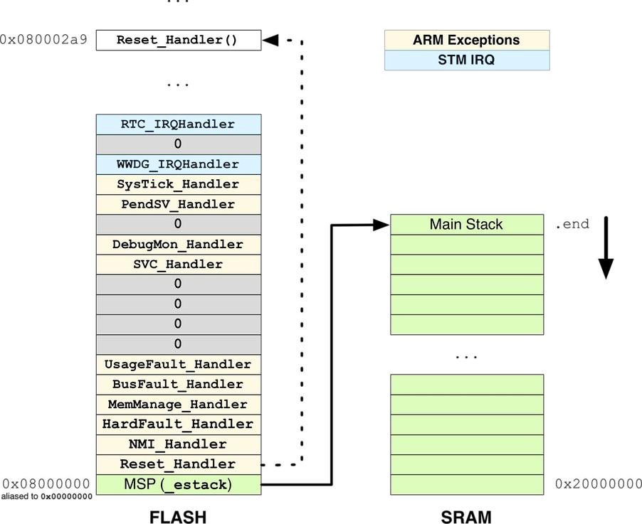
Exception Vector Table#
The Vector Interrupt Table is implemented in assembly code in the startup file of MCU startup_*.s.
  .section .isr_vector,"a",%progbits
  .type g_pfnVectors, %object
  .size g_pfnVectors, .-g_pfnVectors

g_pfnVectors:
  .word _estack                 /* MSP value */
  .word Reset_Handler           /* Reset routine */
  .word NMI_Handler             /* No-Maskable Interrupt */
  .word HardFault_Handler       /* System faults */
  .word MemManage_Handler       /* Memory access issues */
  .word BusFault_Handler        /* Bus access issues */
  .word UsageFault_Handler      /* Instruction/State issues */
  .word 0
  .word 0
  .word 0
  .word 0
  .word SVC_Handler             /* System Service Call */
  .word DebugMon_Handler        /* Serial Wire Debug */
  .word 0
  .word PendSV_Handler          /* Context Switching */
  .word SysTick_Handler         /* System Timer */
  .word WWDG_IRQHandler         /* Window Watchdog interrupt */
  .word PVD_IRQHandler          /* EXTI Line 16 interrupt / PVD through EXTI */
  ...
For convention, the vector table starts at the hardware address 0x00000000 in all Cortex-M based processors. If the vector table resides in the internal flash memory (this is what usually happens), and since the flash in all STM32 MCUs is mapped from 0x08000000 address, alias is used when Boot mode is from Flash to map 0x08000000 to 0x00000000 at CPU boot up.
Read about the Boot mode in the Reference Manual.
Entry zero of this array is the address of the Main Stack Pointer (MSP) inside the SRAM. Usually, this address corresponds to the end of the SRAM _estack.
Exception entry and return#
- Preemption
-
When the processor is executing an exception handler, an exception can preempt the exception handler if its priority is higher than the priority of the exception being handled.When one exception preempts another, the exceptions are called nested exceptions.
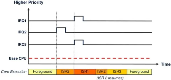
Preemption example with IRQ1 > IRQ2 > IRQ3 - Tail-chaining
-
This mechanism speeds up exception servicing. When an interrupt (exception) is fired, the main (foreground) code context is saved (pushed) to the stack and the processor branches to the corresponding interrupt vector to start executing the ISR handler. At the end of the ISR, the context saved in the stack is popped out, so the processor can resume the main (foreground) code instructions. However, and if a new exception is already pended, the context push & pop are skipped. And the processor handler the second ISR without any additional overhead.
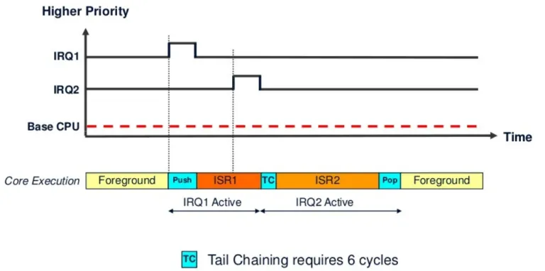
Tail-chaining when IRQ2 comes while IRQ1 is executing - Late-arriving:
-
This mechanism speeds up preemption. If a higher priority exception occurs during state saving for a previous exception, the processor switches to handle the higher priority exception and initiates the vector fetch for that exception. State saving is not affected by late arrival because the state saved is the same for both exceptions. Therefore, the state saving continues uninterrupted. The processor can accept a late arriving exception until the first instruction of the exception handler of the original exception enters to execute stage of the processor. On return from the exception handler of the late-arriving exception, the normal tail-chaining rules apply.
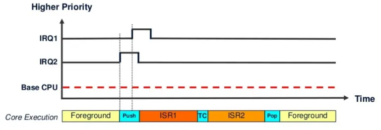
Late arrival is detected when IRQ1 comes while IRQ2 is about to start - Return
-
This occurs when the exception handler is completed, and:
- There is no pending exception with sufficient priority to be serviced
- The completed exception handler was not handling a late-arriving exception
Exception enabling#
By default, not all exceptions and interrupts are enabled to be handled.
| Exception | Default state | Handling behavior |
|---|---|---|
| Reset | Always enabled | Asynchronous |
| NMI | Always enabled | Asynchronous |
| Hard Fault | Always enabled, can be masked | - |
| Memory Fault | Disabled by default | Synchronous |
| Bus Fault | Disabled by default | Synchronous |
| Usage Fault | Disabled by default | Synchronous |
| SVC | Always enabled | Synchronous |
| Debug | Disabled by default | Synchronous |
| PendSV | Disabled by default | Asynchronous |
| SysTick | Disabled by default | Asynchronous |
| Interrupts | Disabled by default | Asynchronous |
For an asynchronous exception other than reset, the processor can execute another instruction between when the exception is triggered and when the processor enters the exception handler.
Nested Vectored Interrupt Controller#
Nested Vectored Interrupt Controller (NVIC) is a method of prioritizing interrupts, improving the MCU’s performance and reducing interrupt latency. NVIC also provides implementation schemes for handling interrupts that occur when other interrupts are being executed or when the CPU is in the process of restoring its previous state and resuming its suspended process.
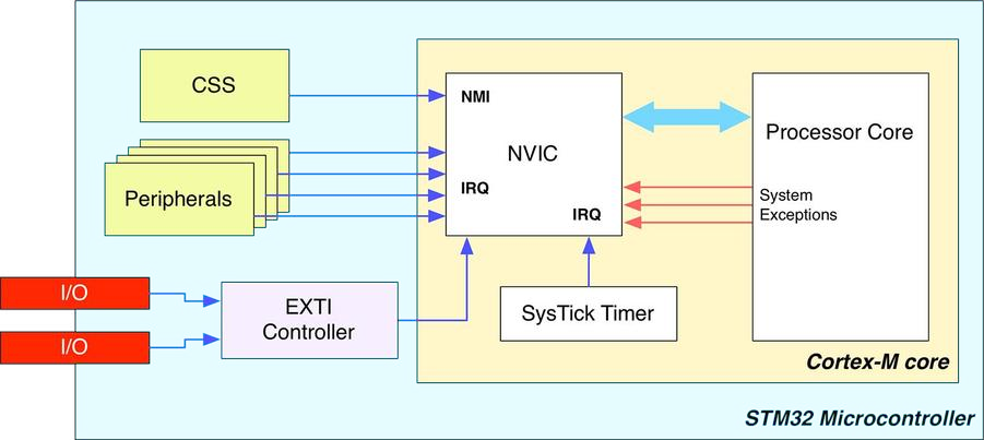
Components that are connected to NVIC inlcude:
- Clock Security System (CSS) interrupt is connected to Non-Maskable Interrupt (NMI) lines
- Peripheral interrupts are connected to Interrupt Requests (IRQ) lines
- GPIO interrupts are connected to an External Interrupt/Event Controller (EXTI) before connecting to the IRQ lines
External Interrupts are grouped by lines which connect to GPIO. As processor may have many GPIOs, an EXTI line is shared by multiple pins. In one line (group), only one pin can be set to generate interrupt, and software must be able to discriminate which lines generated the interrupt.
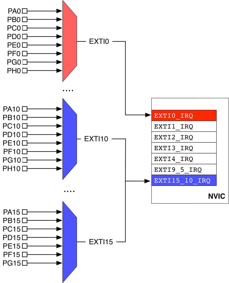
NVIC provides a wide range of register to configure up to 240 interrupts. The IRQ Numbers is defined in the The Vector Interrupt Table.
STM32 interrupts are both level-sensitive and pulse-sensitive. Pulse interrupts are also described as edge-triggered interrupts. The external interrupt can be fired on rising edge, or falling edge, or both.
A level-sensitive interrupt is held asserted until the peripheral de-asserts the interrupt signal. Typically, this happens because the ISR accesses the peripheral, causing it to clear the interrupt request.
A pulse interrupt is an interrupt signal sampled synchronously on the rising edge of the processor clock. To ensure the NVIC detects the interrupt, the peripheral must assert the interrupt signal for at least one clock cycle, during which the NVIC detects the pulse and latches the interrupt.
The Peripheral Pending bit#
When an interrupt takes place, the most of STM32 peripherals assert a specific signal connected to the NVIC, which is mapped in the peripheral memory through a dedicated bit. This Peripheral Pending bit will be held high until it is manually cleared by the application code.
The ISR Pending bit is different to the Peripheral Pending bit:
-
When the processor starts servicing the ISR, the ISR pending bit is cleared automatically
-
The peripheral pending bit will be held high until it is cleared by the application code:
- If the Peripheral Pending bit is not clear, the interrupt will be fired again and the ISR will run again
- It is able to manually set the Peripheral Pending bit to force the ISR run
Exception Lifecycle#
An exception can:
- Either be disabled (default behavior) or enabled;
- either be pending (a request is waiting to be served) or not pending;
- either be in an active (being served) or inactive state.
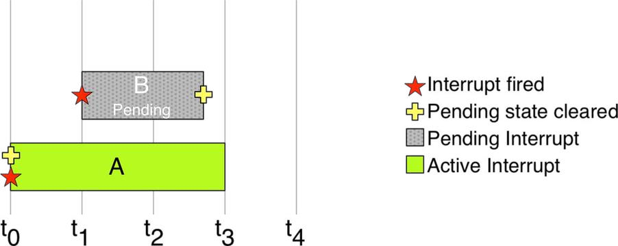
When an exception fires, it is marked as pending until the processor can serve it. If no other exception is currently being processed, it’s pending state is automatically cleared by the processor, then it starts get served.
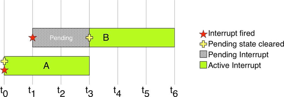
The lower priority ISR has to wait in pending state until no higher priority ISR is being processed. It can be put into inactive state when it is preempted by a higher priority ISR.
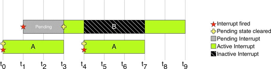
An exception can be forced to fire again during its execution, simply setting its pending bit again. However, the executing exception will complete before re-calling itself.
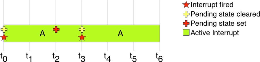
In the same way, the execution of an exception can be canceled clearing its pending bit while it is in pending state.
Exception Behavior#
When an exception occurs, the current instruction stream is stopped and the processor accesses the exceptions vector table:
- The vector address of that exception is loaded from the vector table.
- The exception handler starts to be executed in handler mode.
- The exception handler returns to main (assuming no further nesting).
Here are more details:
Interrupt Stacking (Context Saving)
- The processor will finish the current instruction as long as it’s not a multi-cycle instruction
- The processor state (context) is automatically saved to the stack. Eight registers are pushed (
PC,R0-R3,R12,LR,xPSRand FPU registers). - During or after context saving, the address of the corresponding ISR is loaded from the exception/interrupt vector table
- The link register is modified for return after interrupt
- The first instruction of the ISR starts to be executed by the CPU. For Cortex-M3/M4, the whole latency this process takes is 12 cycles. However, IRQ latency is improved if late-arrival or tail-chaining has occurred.
Interrupt Service Routine (ISR) Handling
- ISR should clear the interrupt source flag if required
- Interrupt nesting won’t affect the way the ISR is written however, attention should be paid to the main stack overflow that may occur.
- Given that certain exceptions/interrupts are to be serviced hundreds or thousands of times per second. So it must run so quickly and no delays are permitted within ISR handlers
Return From ISR (Context Restoration)
- Detect tail-chaining interrupt, if you have, call to the ISR without restoring the context to speed up
- The
EXC_RETURNinstruction is fetched and gets executed to restore the PC and pop the CPU registers. - The return from interrupt (context restoration) on ARM Cortex-M3/M4 requires 10 clock cycles
Example#
Refer to an example in Fault Handler.