Getting started with ESP32 Development Boards
Created by Espressif Systems, ESP32 is a low-cost, low-power system on a chip (SoC) series with Wi-Fi & dual-mode Bluetooth capabilities. ESP32 is highly integrated with built-in antenna switches, RF balun, power amplifier, low-noise receive amplifier, filters, and power management modules. They are engineered for mobile devices, wearable electronics and IoT applications.
Last update: 2022-06-04
Table of Content
Hardware#
The ESP32 chip comes with 48 pins with multiple functions. Not all pins are exposed in all ESP32 development boards, and some pins cannot be used.
The ESP32 is divided by family:
- ESP32: WiFi and BLE
- ESP32-S: WiFi only
- ESP32-C: WiFi and BLE 5
It’s better to start with a dev board having embedded USB-to-Serial port. Please buy a good quality board, and it should be well known, and breadboard-friendly.
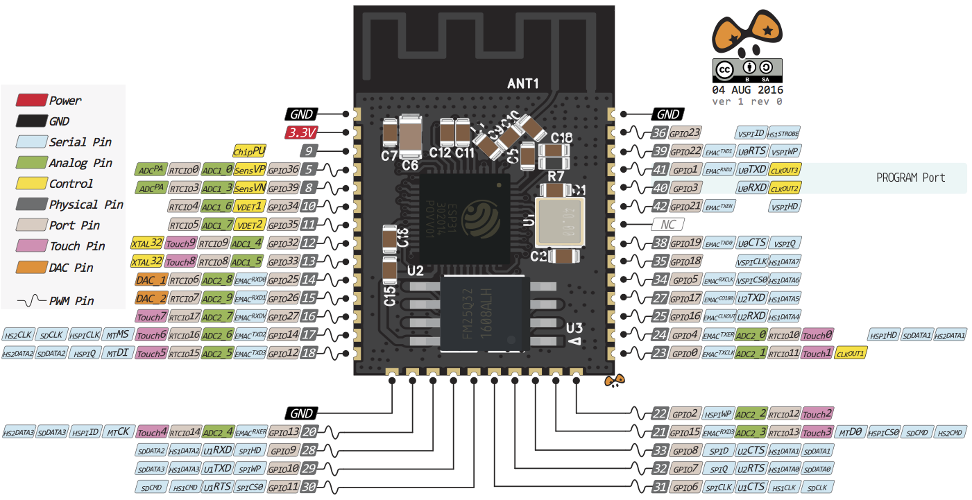
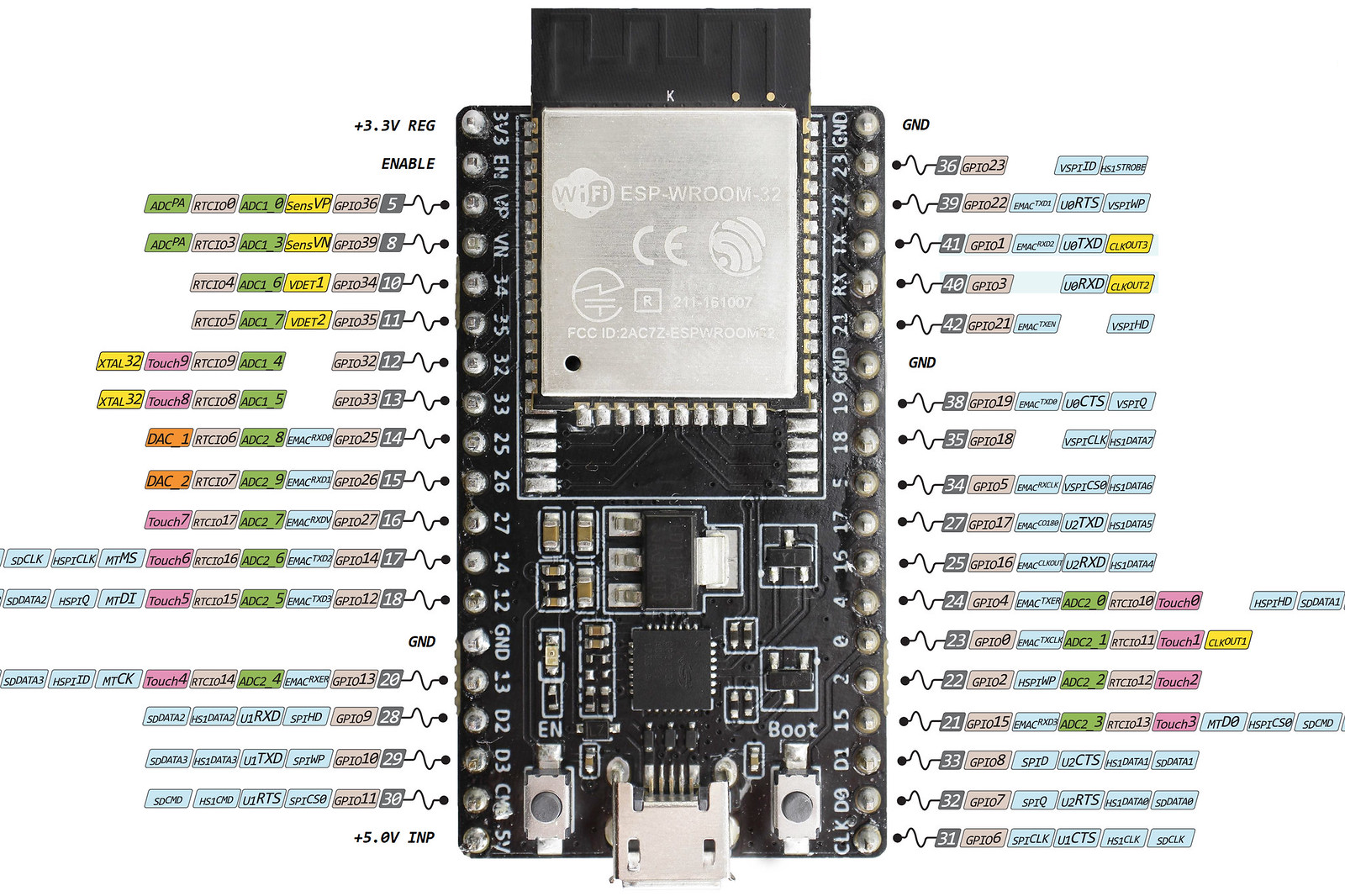
- GPIOs
-
All GPIOs can be configured as interrupts.
GPIO 6 to GPIO 11 are exposed in some ESP32 development boards. However, these pins are connected to the integrated SPI flash on the ESP-WROOM-32 chip and are not recommended for other uses.
Some GPIOs change their state to HIGH or output PWM signals at boot or reset: GPIO 1,3,5, 6-11,14,15.
Enable (EN) is the 3.3 V regulator’s enable pin. It’s pulled up, so connect to ground to disable the 3.3 V regulator. This means that you can use this pin connected to a pushbutton to restart your ESP32, for example.
The absolute maximum current drawn per GPIO is 40 mA according to the “Recommended Operating Conditions” section in the ESP32 datasheet.
- Capacitive touch GPIOs
- The ESP32 has 10 internal capacitive touch sensors on GPIO 0,2,4,12-15,27,32,33. These can sense variations in anything that holds an electrical charge, like the human skin. So they can detect variations induced when touching the GPIOs with a finger. These pins can be easily integrated into capacitive pads and replace mechanical buttons.
- Analog to Digital Converter
- The ESP32 has 18 x 12 bits ADC input channels. ADC2 pins cannot be used when Wi-Fi is used. The ESP32 ADC pins don’t have a linear behavior. You probably won’t be able to distinguish between 0 and 0.1 V, or between 3.2 and 3.3 V.
- Digital to Analog Converter
- There are 2 x 8 bits DAC channels on the ESP32 to convert digital signals into analog voltage signal outputs.
- PWM
- The ESP32 LED PWM controller has 16 independent channels that can be configured to generate PWM signals with different properties. All pins that can act as outputs can be used as PWM pins (GPIOs 34 to 39 can’t generate PWM).
- I2C
- The ESP32 has two I2C channels and any pin can be set as SDA or SCL. SPI0 can be used to access to the external storage unit as a fast cache. SPI1 can be used as the Master host. SPI2, SPI3 can be used as both Master and Slave.
- SPI
-
ESP32 has 4 SPI controllers. They are SPI0, SPI1, SPI2, SPI3.
SPI0 and SPI1 share one BUS prefixed with “SPI”, they consist of signals “D, Q, CS0 ~ CS2, CLK, WP, HD”, and they are not exposed to user.
SPI flash integrated (SPI0, SPI1): GPIOs 34 to 39 are GPIs – input only pins. These pins don’t have internal pull-up or pull-down resistors. They can’t be used as outputs, so use these pins only as inputs
SPI2 and SPI3 use BUS prefixed with “HSPI” and “VSPI” respectively, and they are accessible from user.
- Hall Effect Sensor
- The ESP32 also features a built-in hall effect sensor that detects changes in the magnetic field in its surroundings.
Arduino IDE#
-
Install Arduino IDE and start it.
ESP32 Arduino Core’s documentation from the Espressif manufacturer contains guides and tutorials.
-
Add ESP32 to board managers:
Go to Preferences, then add the below URL:
https://raw.githubusercontent.com/espressif/arduino-esp32/gh-pages/package_esp32_index.json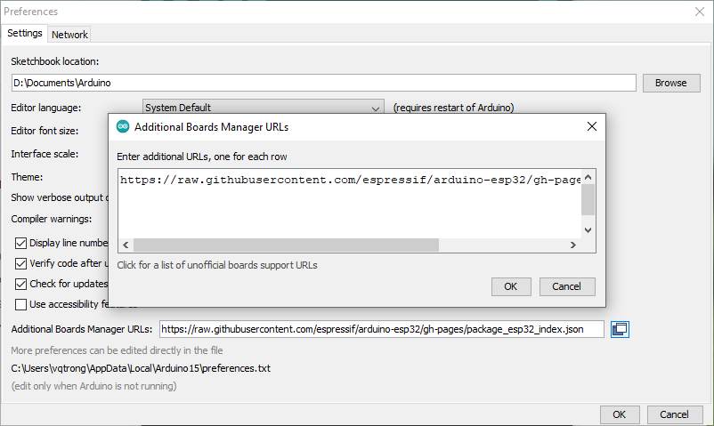
Add a new board to board manager -
Download ESP32 board packages:
Go to Tools → Board → Board Manager and search for
esp32, then install it.
Download Board Support Packages (BSP) -
Example: Blink
Go to Files → Examples → 01. Basics → Blink to create a new sketch:
Blink the built-in LED every second// the setup function runs once when you press reset or power the board void setup() { // initialize digital pin LED_BUILTIN as an output. pinMode(LED_BUILTIN, OUTPUT); } // the loop function runs over and over again forever void loop() { // turn the LED on (HIGH is the voltage level) digitalWrite(LED_BUILTIN, HIGH); delay(500); // turn the LED off by making the voltage LOW digitalWrite(LED_BUILTIN, LOW); delay(500); } -
Select target board
Go to Tools, then under Board → ESP32 Arduino, select your target board, for example, NodeMCU-32S.
You also have to select the COM port, baudrate, and Flash frequency.
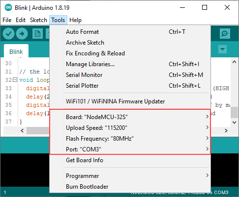
Select ModeMCU-32S as the target board -
Flash and Run
Press Upload to compile and download program to the target board. Press EN button to reset the board and check the user LED.
Fix: Failed to connect to ESP32: Timed out waiting for packet header
Some ESP32 development boards don’t go into flashing/uploading mode automatically when uploading a new code, therefore, you have to Hold the BOOT/FLASH button while uploading programm.
Another way to make your board go into uploading mode automatically is to connect a 10 uF electrolytic capacitor between the EN pin and GND.
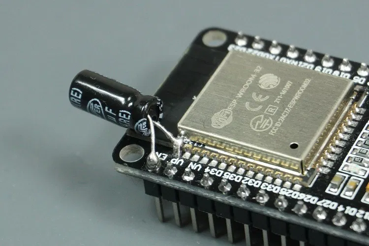
Add 10uF electrolytic capacitor
Espressif ESP32 Libraries#
| Peripheral | ESP32 | ESP32-S2 | ESP32-C3 | Comments |
|---|---|---|---|---|
| ADC | Yes | Yes | Yes | |
| Bluetooth | Yes | Not Supported | Not Supported | Bluetooth Classic |
| BLE | Yes | Not Supported | Yes | |
| DAC | Yes | Yes | Not Supported | |
| Ethernet | Yes | Not Supported | Not Supported | RMII only |
| GPIO | Yes | Yes | Yes | |
| Hall Sensor | Yes | Not Supported | Not Supported | |
| I2C | Yes | Yes | Yes | |
| I2S | Yes | No | No | Work in-progress |
| LEDC | Yes | Yes | Yes | |
| Motor PWM | No | Not Supported | Not Supported | |
| Pulse Counter | No | No | No | |
| RMT | Yes | Yes | Yes | |
| SDIO | No | No | No | |
| SPI | Yes | Yes | Yes | |
| Timer | Yes | Yes | Yes | |
| Temp. Sensor | Not Supported | Yes | Yes | |
| Touch | Yes | Yes | Not Supported | |
| TWAI | No | No | No | |
| UART | Yes | Yes | Yes | |
| USB | Not Supported | Yes | Yes | ESP32-C3 only CDC/JTAG |
| Wi-Fi | Yes | Yes | Yes |
Serial#
Arduino has built-in Serial object that can be used to communicate with the board through the default UART0 port on the target board.
Most of ESP32 Boards has mapped the primary UART0 port to the USB-to-COM chip, therefore, you can easily use the Serial function without any additional board.
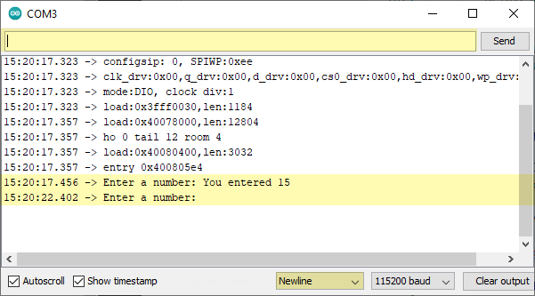
The below example show how to initialize the Serial port and interact with user input:
void setup() {
  // start Serial port
  Serial.begin(115200);
  while (!Serial) {
    ; // wait for serial port to connect. Needed for native USB
  }
}

void loop() {
  // print a message
  Serial.print("Enter a number: ");

  // wait for user input
  while(!Serial.available()) delay(10);

  // read user input, convert it to a number
  int num = Serial.parseInt();

  // look for the newline (enter) character
  // if found, feedback a message
  if (Serial.read() == '\n') {
    Serial.print("You entered ");
    Serial.print(num);
    Serial.println();
  }
}
Flash the program, and open Serial Monitor from Arduino Tools, then you can enter a number to test the application:
LED Control#
The LED control (LEDC) peripheral is primarly designed to control the intensity of LEDs, although it can also be used to generate PWM signals for other purposes.
APIs included:
/* set up */
double ledcSetup(uint8_t channel, double freq, uint8_t resolution_bits);
double ledcChangeFrequency(uint8_t chan, double freq, uint8_t bit_num);
/* pin */
void ledcAttachPin(uint8_t pin, uint8_t chan);
void ledcDetachPin(uint8_t pin);
/* write/read */
void ledcWrite(uint8_t chan, uint32_t duty);
uint32_t ledcRead(uint8_t chan); // return duty
double ledcReadFreq(uint8_t chan);
double ledcWriteTone(uint8_t chan, double freq); // at 50% PWM
double ledcWriteNote(uint8_t chan, note_t note, uint8_t octave);
Example of Fading LED:
#define MIN_BRIGHTNESS    0
#define MAX_BRIGHTNESS    255

#define TIMER_CHANNEL     0
#define TIMER_FREQUENCY   5000
#define TIMER_RESOLUTION  12

int brightness = 0;
int fadeAmount = 5;
int dutyMax = pow(2, TIMER_RESOLUTION) - 1;

void setLedBrightness(uint8_t channel, uint32_t value, uint32_t valueMax = MAX_BRIGHTNESS) {
  uint32_t duty = (dutyMax / valueMax) * min(value, valueMax);
  ledcWrite(channel, duty);
}

void setup() {
  ledcSetup(TIMER_CHANNEL, TIMER_FREQUENCY, TIMER_RESOLUTION);
  ledcAttachPin(LED_BUILTIN, TIMER_CHANNEL);
}

void loop() {
  setLedBrightness(TIMER_CHANNEL, brightness);
  brightness = brightness + fadeAmount;
  if (brightness <= MIN_BRIGHTNESS || brightness >= MAX_BRIGHTNESS) {
    fadeAmount = -fadeAmount;
  }
  delay(10);
}
WiFi Functions#
ESP32 has the main feature of WiFi connection. The official EPS Libraries show all additional drivers for ESP32’s peripherals, including WiFi APIs.
The Wi-Fi API provides support for the 802.11b/g/n protocol driver. This API includes:
- Station mode (STA mode or Wi-Fi client mode). ESP32 connects to an access point
- AP mode (aka Soft-AP mode or Access Point mode). Devices connect to the ESP32
- Security modes (WPA, WPA2, WEP, etc.)
- Scanning for access points
Client Station#
-
Include headers
#include <WiFi.h> -
Connect to a WiFi Network
const char *ssid = "SSID"; const char *password = "password"; void setup() { WiFi.begin(ssid, password); while (WiFi.status() != WL_CONNECTED) { delay(500); } Serial.println(WiFi.localIP()); } -
Create a WiFi Client
const char *host = "192.168.5.94"; const int port = 80; WiFiClient client; if (!client.connect(host, port)) { return; } -
Request to the Web Server
void loop() {
    client.print(
        "GET " + String(request) + " HTTP/1.1\r\n" +
        "Host: " + String(host) + "\r\n" +
        "Connection: close\r\n" +
        "\r\n"
    );
    while(client.available()) {
        String line = client.readStringUntil('\r');
    }
}
Example of Web Server using Python:
- Run on
localhost:80 - Return current time in format
"%H:%M:%S"for each request/time
#!/usr/bin/env python3

import socket
import datetime
import http.server

class ExampleHTTPHandler(http.server.SimpleHTTPRequestHandler):
    def do_GET(self):
        if self.path == '/time':
            self.send_response(200)
            self.send_header('Content-Type', 'text/plain')
            self.end_headers()
            # get current time
            now = datetime.datetime.now().strftime("%H:%M:%S")
            self.wfile.write(now.encode())
            self.wfile.write(b'\r\n')
        else:
            # fallback to default handler
            super().do_GET()

def main():
    print("IP Addresses:")
    for i in socket.getaddrinfo(socket.gethostname(), None):
        print(i[4][0])

    # Run webserver on localhost:80
    server_address = ('', 80)
    # using multithread and ExampleHTTPHandler
    httpd = http.server.ThreadingHTTPServer(server_address, ExampleHTTPHandler)
    print("Server starts")
    httpd.serve_forever()

if __name__ == "__main__":
    main()
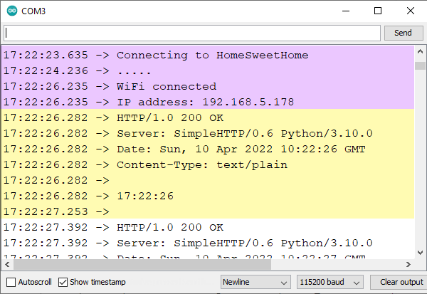
Example of WiFi Web Client:
- Request to URI
/timeon the Web Server athost:port - Print out lines of Web Server’s response
- Note: This example is not optimized (re-create clients in the loop)
#include <WiFi.h>

// Set these to your desired credentials.
const char *ssid = "HomeSweetHome";
const char *password = "password";

// URI
const char *host = "192.168.5.94";
const int   port = 80;
const char *request_time = "/time";

void setup() {
  Serial.begin(115200);
  Serial.println();
  Serial.print("Connecting to ");
  Serial.println(ssid);

  // connect to the WiFi
  WiFi.begin(ssid, password);
  while (WiFi.status() != WL_CONNECTED) {
    delay(500);
    Serial.print(".");
  }

  Serial.println("");
  Serial.println("WiFi connected");
  Serial.print("IP address: ");
  Serial.println(WiFi.localIP());
}

void loop() {
  // Create a client
  WiFiClient client;
  // connect to the host using TCP
  if (!client.connect(host, port)) {
    Serial.println("HTTP connection failed");
    return;
  }

  // send GET request to HTTP Webserver
  client.print(
    "GET " + String(request_time) + " HTTP/1.1\r\n" +
    "Host: " + String(host) + "\r\n" +
    "Connection: close\r\n" +
    "\r\n"
    );

  // wait for response in 5s
  unsigned long timeout = millis();
  while (client.available() == 0) {
    if (millis() - timeout > 5000) {
        Serial.println(">>> Client Timeout !");
        client.stop();
        return;
    }
  }

  //
  // Read all the lines of the reply from server and print them to Serial
  while(client.available()) {
      String line = client.readStringUntil('\r');
      Serial.print(line);
  }

  Serial.println();
}
/time
Soft Access Point#
-
Include headers
#include <WiFi.h> #include <WiFiClient.h> #include <WiFiAP.h> -
Create a WiFi Access Point
const char *ssid = "ESP32-AP"; const char *password = "password"; void setup() { // start the Access Point WiFi.softAP(ssid, password); // get local IP IPAddress myIP = WiFi.softAPIP(); } -
Run a Web Server
WiFiServer server(80); void setup() { // after run the Access Point server.begin(); } void loop() { // listen for incoming clients WiFiClient client = server.available(); if (client) { while (client.connected()) { if (client.available()) { // read data from client char c = client.read(); } } client.stop(); } } -
Response to client
// send header
client.println(
    "HTTP/1.1 200 OK\n"
    "Content-type:text/html\n"
);

// send content
client.println(
    "Hello\n"
);
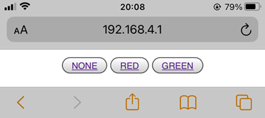
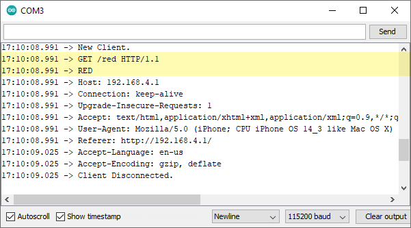
Example of processing user request to change webpage’s background color:
- Web Server listens to user requests in format
GET /<action>,
corresponding to URLs in format<WebServerIP>/<action> - The action could be
redorgreenas the selected color, other actions will clear the color - Show buttons for user to select
#include <WiFi.h>
#include <WiFiClient.h>
#include <WiFiAP.h>

// Set these to your desired credentials.
const char *ssid = "ESP32-AP";
const char *password = "password";

// Run a webser at port 80
WiFiServer server(80);

// A sample webpage show a solid background color
enum BG_COLOR {
  NONE,
  RED,
  GREEN
};

BG_COLOR bg_color = NONE;

const char* red = "red";
const char* green = "green";
const char* none = "initial";

const char *get_bg_color() {
  switch(bg_color) {
    case RED:
      return red;
    case GREEN:
      return green;
    default:
      return none;
  }
}

void send_response(WiFiClient *client) {
  // send Header with OK response
  client->println(
    "HTTP/1.1 200 OK\n"
    "Content-type:text/html\n"
  );

  // send Content
  client->println(
    "<html>"
      "<body "
        "style=\""
          "background-color:" + String(get_bg_color()) + ";"
          "text-align:center;"
      "\">"
        "<a href=\"/\"><button>NONE</a></button>"
        "<a href=\"/red\"><button>RED</a></button>"
        "<a href=\"/green\"><button>GREEN</a></button>"
      "</body>"
    "</html>"
  );
}

void setup() {
  Serial.begin(115200);
  Serial.println();
  Serial.println("Configuring access point...");

  // You can remove the password parameter if you want the AP to be open.
  WiFi.softAP(ssid, password);

  // Show AP address
  IPAddress myIP = WiFi.softAPIP();
  Serial.print("AP IP address: ");
  Serial.println(myIP);

  // Start Web Server
  server.begin();
  Serial.println("Server started");
}

void loop() {
  // listen for incoming clients
  WiFiClient client = server.available();

  if (client) {
    Serial.println("New Client.");
    // string to hold client HTTP request
    String clientString = "";
    while (client.connected()) {
      if (client.available()) {
        char c = client.read();
        //Serial.write(c);

        // newline char means end of string
        if (c == '\n') {
          // if the current line is blank, you got two newline characters in a row.
          // that's the end of the client HTTP request, so send a response:
          if (clientString.length() == 0) {
            send_response(&client);
            // break out of the while loop:
            break;
          } else { // if you got a newline, then process the completed string
            Serial.println(clientString);
            // Check to see if the client request was "GET /red" or "GET /green":
            if (clientString.startsWith("GET /red ")) {
              Serial.println("RED");
              bg_color = RED;
            } else if (clientString.startsWith("GET /green ")) {
              Serial.println("GREEN");
              bg_color = GREEN;
            } else if (clientString.startsWith("GET / ")) {
              Serial.println("NONE");
              bg_color = NONE;
            }
            clientString = "";
          }
        } else if (c != '\r') {  // if you got anything else but a carriage return character,
          clientString += c;      // add it to the end of the currentLine
        }
      }
    }
    // close the connection:
    client.stop();
    Serial.println("Client Disconnected.");
  }
}
/red
Preferences (Saved Data)#
The Preferences library is unique to arduino-esp32. It should be considered as the replacement for the Arduino EEPROM library.
It uses a portion of the on-board non-volatile memory (NVS) of the ESP32 to store data. This data is retained across restarts and loss of power events to the system.
Preferences works best for storing many small values, rather than a few large values. If large amounts of data are to be stored, consider using a file system library such as LitteFS.
Data is saved in below format:
namespace {
  key1: value1
  key2: value2
}
-
Include header and initiate an instance:
#include <Preferences.h> Preferences preferences; -
Begin a namespace
bool begin(const char * name, bool readOnly=false, const char* partition_label=NULL) -
Read/Write data
Note: Key name is limited to 15 chars.
size_t put<Type>(const char* key, <Type> value); size_t get<Type>(const char* key, <Type> defaultValue = 0); bool remove(const char * key); PreferenceType getType(const char* key); -
Clear data
bool clear() -
Close session
bool clear()
Namespace
In the Arduino implementation of Preferences, there is no method of completely removing a namespace. As a result, over the course of several projects, the ESP32 non-volatile storage (nvs) Preferences partition may become full. To completely erase and reformat the NVS memory used by Preferences, create a sketch that contains:
#include <nvs_flash.h>

void setup() {
    nvs_flash_erase(); // erase the NVS partition and...
    nvs_flash_init(); // initialize the NVS partition.
}

void loop() {}
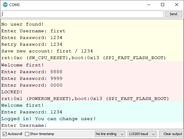
Example to save username/password:
- If no user found, add a new user
- If an user exists, prompt for the password
- If the password is correct, allow changing user
- If password is incorrect 3 times, lock the machine
#include <Preferences.h>
Preferences preferences;

#define NS_ACCOUNT "account"
#define KEY_USER "user"
#define KEY_PASSWD "passwd"

/*
 account {
    user: XXX
    passwd: YYY
 }
*/

String user;
String passwd;
String passwd2;

void input(String& prompt, String& str) {
  str = "";
  Serial.print(prompt);
  while(str == ""){
    str = Serial.readString();
  }
  Serial.println(str);
}

void addUser() {
  while(true) {
    String prompt="Enter Username: ";
    input(prompt, user);

    prompt="Enter Password: ";
    input(prompt, passwd);

    prompt="Retry Password: ";
    input(prompt, passwd2);

    if (passwd == passwd2) {
      int r = -1;
      Serial.println("Save new account: " + user + " / " + passwd);
      r = preferences.putString(KEY_USER, user);
      if (r == 0) Serial.println("Can NOT user!");

      r = preferences.putString(KEY_PASSWD, passwd);
      if (r == 0) Serial.println("Can NOT passwd!");

      preferences.end();
      delay(1000);

      ESP.restart();
    }
  }
}

void askPassword() {
  Serial.println("Welcome " + user + "!");

  passwd = preferences.getString(KEY_PASSWD);

  int trial = 3;
  String prompt="Enter Password: ";

  while(trial > 0) {
    input(prompt, passwd2);
    trial--;

    if(passwd == passwd2) {
      break;
    }
  }

  if (trial > 0) {
    Serial.println("Logged in! You can change user!");
    addUser();
  } else {
    Serial.println("LOCKED!");
    while(true){}
  }
}

void setup() {
  Serial.begin(115200);
  while (!Serial) {}

  // open namespace NS_ACCOUNT with readOnly = false
  preferences.begin(NS_ACCOUNT, false);

  user = preferences.getString(KEY_USER);
  if (user == "") {
    Serial.println("No user found!");
    addUser();
  }
  else {
    askPassword();
  }
}

void loop() {
  delay(1000);
}